

Edit October 2023: The Tolerance (Accuracy) Classes edited per IEC 60751:2022.
Edit November 2025: Added Pt100 vs Pt1000 comparison
Pt100 temperature sensors are very common sensors in the
A while back I wrote about thermocouples, so I was thinking it’s time to write about RTD temperature sensors, especially on the Pt100 sensor which is a very common temperature sensor. This blog ended up being pretty long as there is a lot of useful information to share. I hope you like it and that you learn something from it. Let’s get into it!
Table of contents
- RTD temperature sensors
- PRT temperature sensors
- PRTs versus thermocouples
- Measuring RTD/PRT sensor
- Measurement current
- Self-heating
- Different mechanical structures of PRT sensors
- SPRT
- Partially supported PRT
- Industrial Platinum Resistance Thermometers, IPRT’s
- Film
- Other RTD sensors
- Other Platinum sensors
- Other RTD sensors
- Pt100 sensors
- Temperature coefficient
- Pt100 (385) temperature resistance relationship
- Other Pt100 sensors with different temperature coefficients
- Make sure your measurement device supports your Pt100 sensor
- Pt100 accuracy (tolerance) classes
- Coefficients
- Callendar-van Dusen
- ITS-90
- Steinhart-Hart
- Pt100 vs Pt1000
- Other temperature-related blog posts
- Beamex temperature calibration products
A note on terminology, both “sensor” and “probe” are widely used, I mainly use “sensor” in this article.
Also, "Pt100" and "Pt-100" are both being used, but I will mainly use the Pt100 format. (Yep, I know that IEC / DIN 60751 uses Pt-100, but I am so used to writing Pt100).
Just give me this article in pdf format! Click the link below to download pdf:

RTD temperature sensors
As the Pt100 is an RTD sensor, let’s look first at what an RTD sensor is.
The abbreviation RTD is short for “Resistance Temperature Detector.” So it is a temperature sensor in which the resistance depends on temperature; when the temperature changes, the sensor’s resistance changes. So, by measuring the RTD sensor’s resistance, an RTD sensor can be used to measure temperature.
RTD sensors are most commonly made from platinum, copper, nickel alloys, or various metal oxides and the Pt100 is one of the most common.
PRT temperature sensors
Platinum is the most common material for RTD sensors. Platinum has a reliable, repeatable, and linear temperature-resistance relationship. RTD sensors made of platinum are called PRT, “Platinum Resistance Thermometer.” The most common PRT sensor used in the process industry is the Pt100 sensor. The number “100” in the name indicates that is has a resistance of 100 ohms at 0°C (32°F) temperature. More details on that later.
PRTs versus thermocouples
In an earlier blog post, we discussed thermocouples, which are also used as temperature sensors in many industrial applications. So, what’s the difference between a thermocouple and a PRT sensor? Here’s a short comparison:
Thermocouples:
- Can be used to measure much higher temperatures
- Very robust
- Inexpensive
- Self-powered, does not need external excitation
- Not very accurate
- Requires cold junction compensation
- Extension wires must be made of suitable material for the thermocouple type
- Attention must be paid to temperature homogeneity across all junctions in the measurement circuit
- Inhomogeneities in wires may cause unexpected errors
PRTs:
- More accurate, linear and stable than thermocouples
- Do not require cold junction compensation
- Extension wires can be made of copper
- More expensive than thermocouples
- Need a known excitation current suitable for the sensor type
- More fragile
In short, thermocouples are more suitable for high-temperature applications and PRTs for applications that require better accuracy.
More information on thermocouples and cold junction compensation can be found in this earlier blog post:
Thermocouple Cold (Reference) Junction Compensation
Measuring a RTD/PRT sensor
Since an RTD sensor’s resistance changes when the temperature changes, it is pretty clear that when measuring the RTD sensor you need to measure resistance. You can measure the resistance in Ohms then convert that manually into a temperature measurement according to the conversion table (or formula) of the RTD type being used.
More commonly nowadays, you use a temperature measurement device or calibrator that automatically converts the measured resistance into a temperature reading. This requires the correct RTD type to be selected in the device (assuming it supports the RTD type used). If the wrong RTD sensor type is selected, it will result in incorrect temperature measurement results.
There are different ways to measure resistance. You can use a 2, 3, or 4 wire connection. The 2-wire connection is only suitable for very low accuracy measurement (mainly troubleshooting) because any wire resistance or connection resistance will introduce error to the measurement.
Sure for some high-impedance thermistors, Pt1000 sensors, or other high-impedance sensors, the additional error caused by the 2-wire measurement may not be too significant.
Any normal process measurement should be done using 3 or 4 wire measurement.
For example, the IEC 60751 standard specifies that any sensor with higher than class B accuracy must be measured using a 3 or 4 wire measurement. More on the accuracy classes later in this article.
Just remember to use a 3 or 4 wire measurement and you are good to go.
More information on 2, 3, and 4 wire resistance measurement can be found in the blog post below:
Resistance measurement; 2, 3 or 4 wire connection – How does it work and which to use?
Measurement current
As explained in the above-linked blog post in more detail, when a device is measuring resistance it sends a small accurate current through the resistor and then measures the voltage drop generated over it. The resistance can then be calculated by dividing the voltage drop by the current according to Ohm’s law (R=U/I).
If you are interested in more detailed info on Ohm’s law, check out this blog post:
Ohm’s law – what it is and what an instrument tech should know about it
Self-heating
When the measurement current goes through the RTD sensor, it also causes the RTD sensor to warm slightly. This phenomenon is called self-heating. The higher the measurement current and the longer it is on, the more the sensor will warm. The sensor’s structure and its thermal resistance to its surroundings will also have a big effect on the self-heating. It is pretty obvious that this kind of self-heating in a temperature sensor will cause a small measurement error.
The measurement current is typically a max of 1 mA when measuring a Pt100 sensor, but it can be as low as 100 µA or even lower. According to standards such as IEC 60751, self-heating must not exceed 25% of the sensor’s tolerance specification.
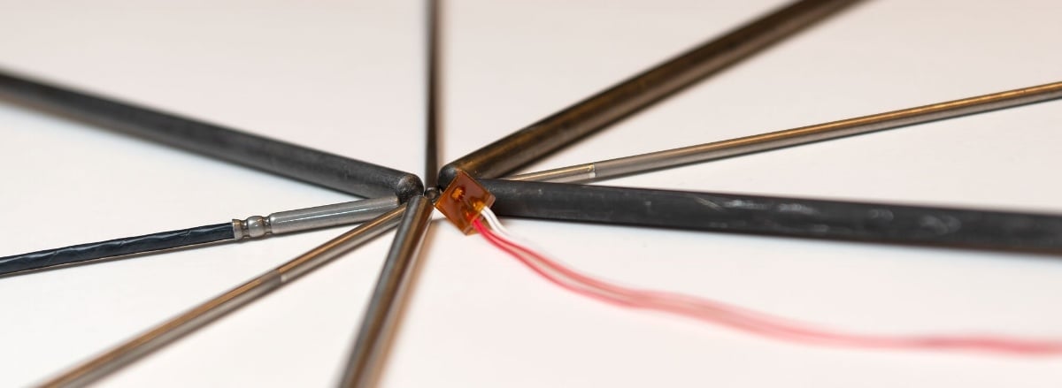
Mechanical structures of PRT sensors
PRT sensors are generally very delicate instruments and unfortunately, accuracy is almost without exception inversely proportional to mechanical robustness. To be an accurate thermometer, the platinum wire inside the element should be able to contract and expand as freely as possible as the temperature changes to avoid strain and deforming. The drawback is that this sort of sensor is very sensitive to mechanical shocks and vibration.
Standard Platinum Resistance Thermometer (SPRT)
Standard Platinum Resistance Thermometer (SPRT) sensors are highly accurate instruments for realizing the ITS-90 temperature scale between fixed points. They’re made from very pure (α = 3,926 x 10-3 °C-1) platinum and the wire support is designed to keep the wire as strain-free as possible. The “Guide to the Realization of the ITS-90” published by the Bureau International des Poids et Mesures (BIPM) defines the criteria that SPRT sensors must fulfill. Other sensors are not and should not be called SPRTs. There are glass, quartz, and metal sheathed sensors for different applications. SPRTs are extremely sensitive to any kind of acceleration such as tiny shocks and vibrations, which limits their use to laboratories requiring the very highest accuracy measurements.
Partially supported PRTs
Partially supported PRTs are a compromise between thermometer performance and of mechanical robustness. The most accurate PRTs are often called Secondary Standard or Secondary Reference sensors. These sensors may adopt some structures from
Industrial Platinum Resistance Thermometers, IPRTs
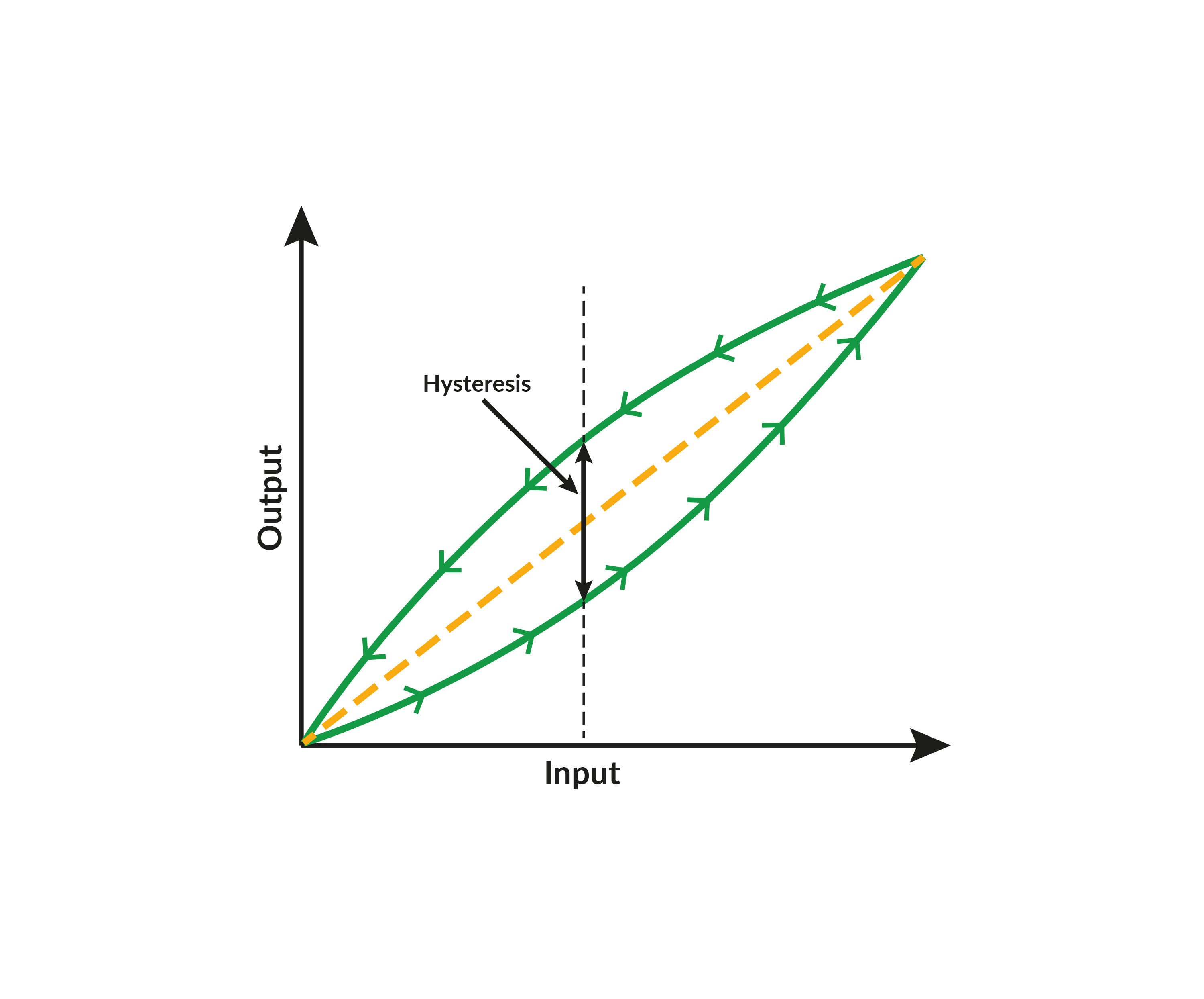
When the wire support is increased, the mechanical robustness increases, but so does the strain from drift and hysteresis issues. Fully supported Industrial Platinum Resistance Thermometers (IPRTs) have even more wire support and are mechanically very robust. The wire is encapsulated completely in ceramic or glass, making it highly resistant to vibration and mechanical shocks. The drawback is much poorer long-term stability and large hysteresis as the sensing platinum is bonded to the substrate, which has different thermal expansion characteristics.
Film PRTs
Film PRTs have evolved a lot in recent years and better ones are now available. They come in many forms for different applications. The platinum foil is sputtered onto the selected substrate; the resistance of the element is often laser-trimmed to the desired resistance value and eventually encapsulated for protection. Unlike wire elements, thin film elements make it easier to automate the manufacturing process, which makes them often cheaper than wire elements. The advantages and disadvantages are typically the same as with fully supported wire elements except that film elements often have a very low time constant, meaning that they react very fast to temperature changes. As mentioned earlier, some manufacturers have developed techniques that better combine performance and robustness.
Other RTD sensors
Other platinum sensors
Although the Pt100 is the most common platinum RTD/PRT sensor, there are several others such as the Pt25, Pt50, Pt200, Pt500, and Pt1000. The main difference between these sensors is pretty easy to guess; it is the sensor's resistance at 0°C, which is mentioned in the name. For example, a Pt1000 sensor has a
Other RTD sensors
Although platinum sensors are the most common, there are also RTD sensors made of other materials including nickel, nickel-iron and copper. Common nickel sensors include the Ni100 and Ni120, an example of a nickel-iron sensor is the Ni-Fe 604-ohm and a common copper sensor is the Cu10. These materials each have their ownadvantages in certain applications. Common disadvantages are rather narrow temperature ranges and susceptibility to corrosion compared to the noble metal platinum.
RTD sensors can also be made with other materials like gold, silver, tungsten, rhodium-iron or germanium. They excel in some applications but are very rare in normal industrial operations.
Since an RTD sensor’s resistance depends on temperature, we could also include all generic positive temperature coefficient (PTC) and negative temperature coefficient (NTC) sensors in this category. Examples of these are thermistors and semiconductors that are used for measuring temperature. NTC sensors are especially common to use for measuring temperature.
Need a break? Download this article as a pdf to read when you have more time - just lick the picture below.

Pt100 sensors
Temperature coefficient
The most common RTD sensor in the process industry is the Pt100 sensor, which has a resistance of 100 ohms at 0°C (32°F).
With the same logical naming convention, a Pt200 sensor has a resistance of 200 ohms and a Pt1000 has a resistance of 1000 ohms at 0°C (32°F).
The resistance of the Pt100 sensor (and other Pt sensors) at higher temperatures depends on the sensor version, as there are a few different ones with slightly different temperature coefficients. Globally, the most common is the 385 version. If the coefficient is not mentioned, it is typically the 385.
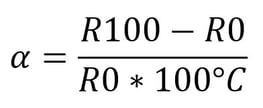
The temperature coefficient (indicated by the Greek letter Alpha => α) of the Pt100 sensor is the difference between the resistance at 100°C and 0°C, divided by the resistance at 0°C multiplied by 100°C.
The formula is pretty simple, but it does sound a bit complicated when written, so let’s look at it as a formula:
Let’s take a look at an example to make sure this is clear:
Pt100 has a resistance of 100.00 ohms at 0°C and a resistance of 138.51 ohms at 100°C. The temperature coefficient can be calculated with the following equation:
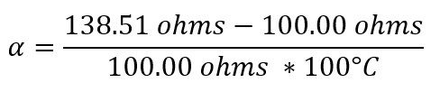
We get a result of 0.003851 /°C.
Or as it is often written: 3.851 x 10⁻³ °C-1
Often this figure is rounded and the sensor is referred to as a “385” Pt100 sensor.
This is also the temperature coefficient specified in the IEC 60751:2008 standard.
The temperature coefficient of the sensor element mostly depends on the purity of the platinum used to make the wire. The purer the platinum, the higher the alpha value. Nowadays it’s not a problem to get
The alpha value originates from when the melting point (≈0 °C) and the boiling point (≈100 °C) of water were used as reference temperature
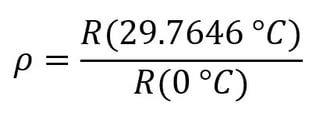
A typical ρ value for a 385 sensor is 1.115817 and for an SPRT it is 1.11814. In practice, the good old alpha is, in many cases, the most convenient, but
Pt100 (385) temperature resistance relationship
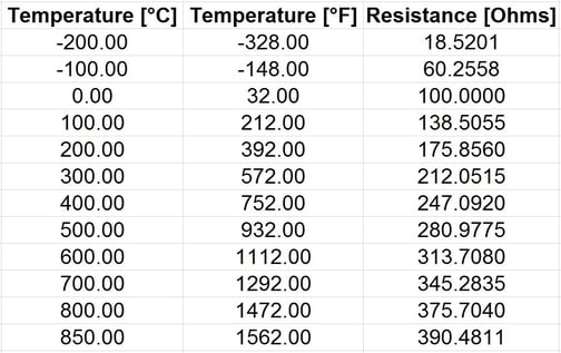
In the graph below, you can see how a Pt100 (385) sensor’s resistance depends on temperature:
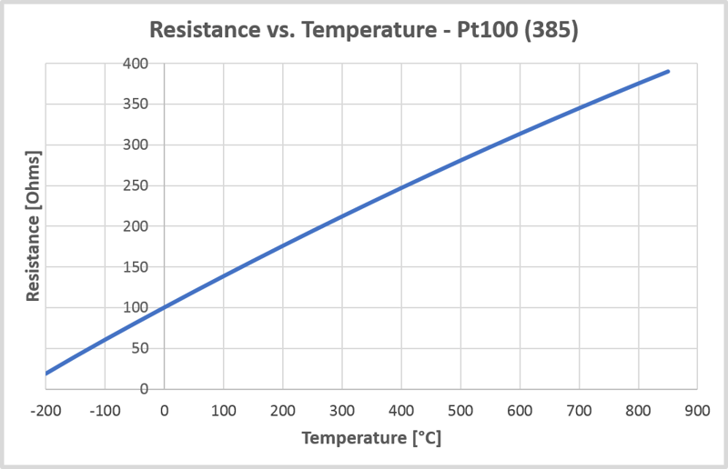
When looking at these, you can see that the resistance-temperature relationship of a Pt100 sensor is not perfectly linear, but the relationship is somewhat curved.
The table below shows the numerical values of a Pt100 (385) temperature vs. resistance at a few points:
Other Pt100 sensors with different temperature coefficients
Most sensors have been standardized, but there are different standards around the world. This is also the case with Pt100 sensors. Over time, there have been a few different standards specified. In most cases, there is only a relatively small difference in the temperature coefficient.
As a practical example, the standards that we have implemented in Beamex temperature calibrators include the following:
- IEC 60751
- DIN 43760
- ASTM E 1137
- JIS C1604-1989 alpha 3916, JIS C 1604-1997
- SAMA RC21-4-1966
- GOCT 6651-84, GOST 6651-94
- Minco Table 16-9
- Edison curve #7
Make sure your measurement device supports your Pt100 sensor
The good thing about standard Pt100 probes is that each sensor should fulfill the specifications and you can just plug it into your measurement device or calibrator and it will measure its own temperature as accurately as the specifications (sensor + measurement device) define. Sensors in the process should be interchangeable without calibration, at least for less critical measurements. Nevertheless, it would still be good practice to check the sensor at some known temperature before use.
Anyhow, since the different standards have slightly different specifications for the Pt100 sensor, it is important that the device you use for measuring your Pt100 sensor supports the correct temperature coefficient. For example, if your measuring device supports only Alpha 385 and you are using a sensor with an Alpha 391, there will be some error in the measurement. Is that error significant? In this case (385 vs 391), the error would be roughly 1.5°C at 100°C. So I think it is significant. Of course, the smaller the difference between temperature coefficients, the smaller the error will be.
So make sure that your RTD measurement device supports the Pt100 probe you are using. Most often if the Pt100 has no indication of the temperature coefficient, it is a 385 sensor.
As a practical example, the Beamex MC6 calibrator & communicator supports the following Pt100 sensors (temperature coefficient in parenthesis) based on different standards:
- Pt100 (375)
- Pt100 (385)
- Pt100 (389)
- Pt100 (391)
- Pt100 (3926)
- Pt100 (3923)
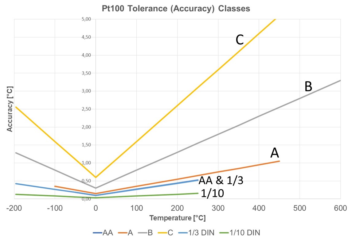
Pt100 accuracy (tolerance) classes
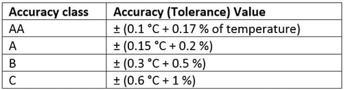
Pt100 sensors are available in different accuracy classes, the most common of which are AA, A, B and C being defined in the IEC 60751 standard. Standards define a sort of ideal Pt100 sensor for the manufacturers to aim at. If it was possible to build the ideal sensor, tolerance classes would be irrelevant.
As Pt100 sensors cannot be adjusted to compensate for errors, you should buy a sensor with a suitable accuracy for your application. Sensor errors can be corrected in some measurement devices with certain coefficients, but more on that later.
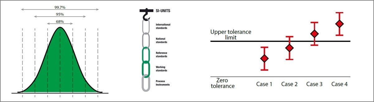
The accuracy (tolerance) values of the different accuracy classes (IEC 60751:2022):
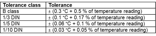
There are also so-called fraction tolerance classes, such as 1/3, 1/5 and 1/10. They were earlier standardized classes in, for example, DIN 43760:1980-10 that was withdrawn in 1987, but they were not defined in the later IEC 60751 standard.
Anyhow, the IEC 60751:2022 standard defines these tolerance classes in section 5.2.3.3 (Marking of thermometers). The tolerance of these sensors is based on the accuracy class B sensor, but both the fixed part (0.3 °C) and the relative part of the error are divided by the given number (3, 5 or 10). So, the tolerance classes of these sensors are:
And of course, a sensor manufacturer can manufacture sensors with their own custom accuracy classes.
The formulas can be difficult to compare, so in the below table the accuracy classes are calculated according to temperature (°C):
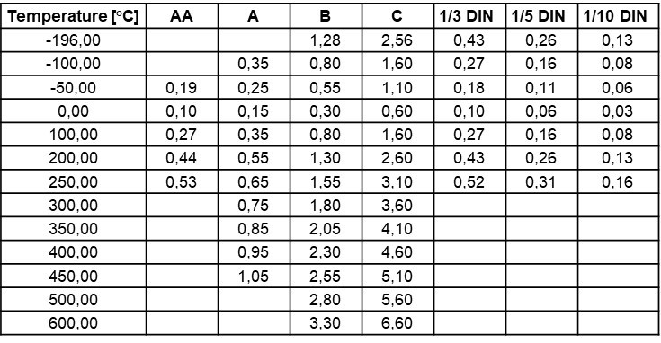
The graphic below shows the difference between these accuracy classes:
Coefficients
The accuracy classes are commonly used in industrial RTD sensors, but when it comes to the most accurate PRT reference sensors (SPRT, Secondary Standards, etc.), those accuracy classes are not valid anymore. These sensors were made to be as good as a thermometer as possible for the purpose, not to match any standardized curve. They are very accurate sensors with very good long-term stability and very low hysteresis, but each sensors is unique, so each sensor has a slightly different temperature/resistance relationship. These sensors should not be used without their own specific coefficients. You can find general CvD coefficients for SPRT’s, but that will ruin the performance you’ve paid for. If you just plug in a
To sum up: PRT reference sensors must always be used with proper coefficients.
As mentioned before, RTD sensors cannot be “adjusted” to measure correctly. Instead, the correction needs to be made in the device (for example the temperature calibrator) that is being used to measure the RTD sensor.
In order to find out the coefficients, the sensor should first be calibrated very accurately. The calibration provides the coefficients for the desired equation, which can be used to represent the sensor’s characteristic resistance/temperature relationship. The use of the coefficients will correct the sensor measurement and will ensure it measures accurately. There are several different equations and coefficients to calculate the sensor’s resistance to temperature. These are probably the most widespread:
Callendar-van Dusen
- In the late 19th century, Callendar introduced a simple quadratic equation that describes the resistance/temperature behavior of platinum. Later, van Dusen found out that an additional coefficient was needed below zero. It’s known as the Callendar-van Dusen equation (CvD). For alpha 385 sensors, it’s often about as good as ITS-90, especially when the temperature range isn’t very wide. If your certificate states coefficients R0, A, B, C, they are coefficients for the IEC 60751 standard form CvD equation. Coefficient C is only used below 0 °C, so it may be absent if the sensor was not calibrated below 0 °C. The coefficients may also be R0, α, δ
and β. They fitto the historically used form of the CvD equation that is still in use. Regardless of being essentially the same equation, their written form and coefficients are different.
ITS-90
- ITS-90 is a temperature scale, not a standard. The Callendar-van Dusen equation was the basis of the previous scales of 1927, 1948 and 1968, but ITS-90 brought significantly different mathematics. ITS-90 functions must be used when realizing the temperature scale using SRPTs, but many lower-alpha PRTs also benefit from it compared to CvD, especially when the temperature range is wide (covers hundreds of degrees). If your certificate states coefficients like RTPW or R(0,01), a4, b4, a7, b7, c7, they are coefficients for ITS-90 deviation functions. The ITS-90 document does not designate numerical notations for the coefficients or subranges. They are presented in NIST Technical Note 1265 "Guidelines for Realizing the International Temperature Scale of 1990" and widely adopted for use. The number of coefficients may vary and the subranges are numbered 1…11.
- RTPW, R(0,01 °C) or R(273,16 K) is the sensor’s resistance at the triple point of water 0,01 °C
- a4 and b4 are coefficients below zero, may also be
a bz andb bz meaning “below zero”, or just a and b - a7, b7 and c7 are coefficients above zero, may also be
a az , bazand c az meaning “above zero”, or a, b and c
Steinhart-Hart
- If your sensor is a thermistor, you may have Steinhart-Hart equation coefficients on the certificate. Thermistors are highly non-linear and the equation is logarithmic. The Steinhart-Hart equation has widely replaced the earlier Beta-equation.
Usually the coefficients are A, Band C, but there may also be coefficient D or others, depending on the variant of the equation. The coefficients are usually published by manufacturers, but they can be fitted as well.
Finding out the sensor coefficients
When a Pt100 sensor is sent to a laboratory for calibration and fitting, the calibration points must be selected properly. A 0 °C or 0.01 °C point is always needed. The value itself is needed for fitting but typically ice point (0 °C) or the triple point of water cells (0.01 °C) is used to monitoring the stability of the sensor and is measured several times during calibration. The minimum number of calibration points is the same as the number of coefficients that should be fitted. For example, for fitting ITS-90 coefficients a4 and b4 below zero, at least two known negative calibration points are needed to solve the two unknown coefficients. If the sensor’s behavior is well known to the laboratory, two points might be enough in this case. Nevertheless, it’s a good practice to measure more points than absolutely necessary, because there’s no other way the certificate can tell how the sensor behaves between the calibration points. For example, CvD fitting for a wide temperature range may look good if you only have two or three calibration points above zero, but there may be a systematic residual error of several hundredths of a degree between calibration points that you won’t see at all. This also explains why you may find different calibration uncertainties for CvD and ITS-90 fitting for the same sensor and the exact same calibration points. The uncertainties of the measured points are no different, but the residual errors of different fittings are usually added to the total uncertainty.
While the Pt100 is by far the most common platinum RTD used in industrial applications, there’s also a variant called the Pt1000 that’s based on the same principle but has some practical differences. Let's shortly take a closer look at the differences next.
Pt100 vs Pt1000
What is the difference between Pt100 and Pt1000?
Pt100 has 100 Ω resistance at 0°C, while Pt1000 has 1000 Ω. Pt1000 sensors are less affected by lead wire resistance, use lower measurement current, and cause less self-heating. Pt100 is common in industrial process applications, and Pt1000 in HVAC and smaller systems.
Both Pt100 and Pt1000 sensors are platinum resistance temperature detectors (RTDs) that work on the same principle: their electrical resistance changes predictably with temperature. The main difference lies in their nominal resistance: a Pt100 sensor has a resistance of 100 ohms at 0°C, while a Pt1000 sensor has 1000 ohms at 0°C.
That tenfold increase in resistance has a few practical implications.
First, because the resistance is higher, the impact of any small resistance error (for example, from the measurement circuit or lead wires) is proportionally smaller in a Pt1000 sensor. In other words, a given resistance uncertainty has less effect on the temperature reading.
Also, since the resistance is higher, a smaller measurement current can be used to generate a readable voltage signal. Using less current means less self-heating of the sensor element, which helps improve measurement accuracy, especially in air or low-conductivity environments.
Typical differences at a glance
- Nominal resistance at 0°C: 100 Ω for Pt100, 1000 Ω for Pt1000
- Typical measurement current: around 1 mA for Pt100, about 0.1 mA for Pt1000
- Sensitivity to lead wire resistance: Pt100 is more sensitive; Pt1000 is less affected
- Self-heating: Pt100 may have slightly higher self-heating; Pt1000 lower
- Typical use: Pt100 is common in industrial process applications; Pt1000 often used in HVAC, building automation, and compact devices
- Cost: Pt100 is usually slightly cheaper, while Pt1000 can cost a bit more
Wiring considerations
Because the Pt100 sensor’s resistance is lower, lead wire resistance has a more noticeable effect on measurement accuracy — especially in 2-wire configurations. Pt1000 sensors can offer better accuracy in simple 2-wire systems since the relative influence of the lead resistance is smaller.
However, in most industrial applications where 3-wire or 4-wire configurations are used (which compensate for lead resistance), the Pt100 remains the preferred choice. These wiring methods effectively eliminate lead resistance effects, making Pt100 sensors extremely reliable and widely supported by transmitters and calibration equipment.
Applications
- Pt100: The traditional and most common choice in industrial process instrumentation and calibration. Ideal for environments with long cable runs and where standardized transmitters and high accuracy are required.
- Pt1000: Often used in HVAC systems, building automation, and smaller devices where shorter cable runs and simple 2-wire connections are sufficient, and minimizing self-heating is beneficial.
Accuracy and interchangeability
Both sensor types share the same platinum temperature coefficient (α = 0.00385 Ω/Ω/°C) defined by IEC 60751, so the fundamental accuracy and stability are the same. The difference is mainly electrical, not physical.
That said, Pt100 and Pt1000 sensors are not directly interchangeable, the measurement circuit or transmitter must be configured for the correct sensor type to ensure accurate readings.
Summary
In short, both Pt100 and Pt1000 sensors provide excellent accuracy and long-term stability when used correctly. The right choice depends mainly on your application and wiring setup:
- Pt100 is the proven standard for process industries and calibration work.
- Pt1000 can be a good fit for smaller systems, shorter cables, or applications where lower measurement current and reduced self-heating are preferred.
Download the free white paper
Download our free white paper on Pt100 temperature sensors by clicking the picture below:

Other temperature-related blog posts
If you are interested in temperature and temperature calibration, you may find these other blog posts interesting:
- Thermocouple Cold (Reference) Junction Compensation
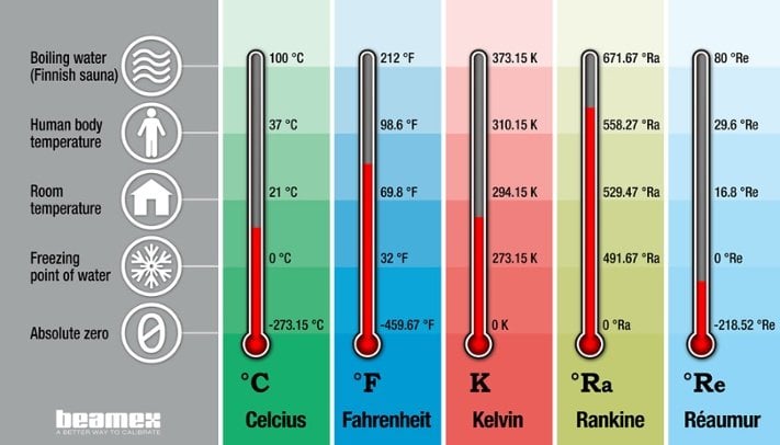
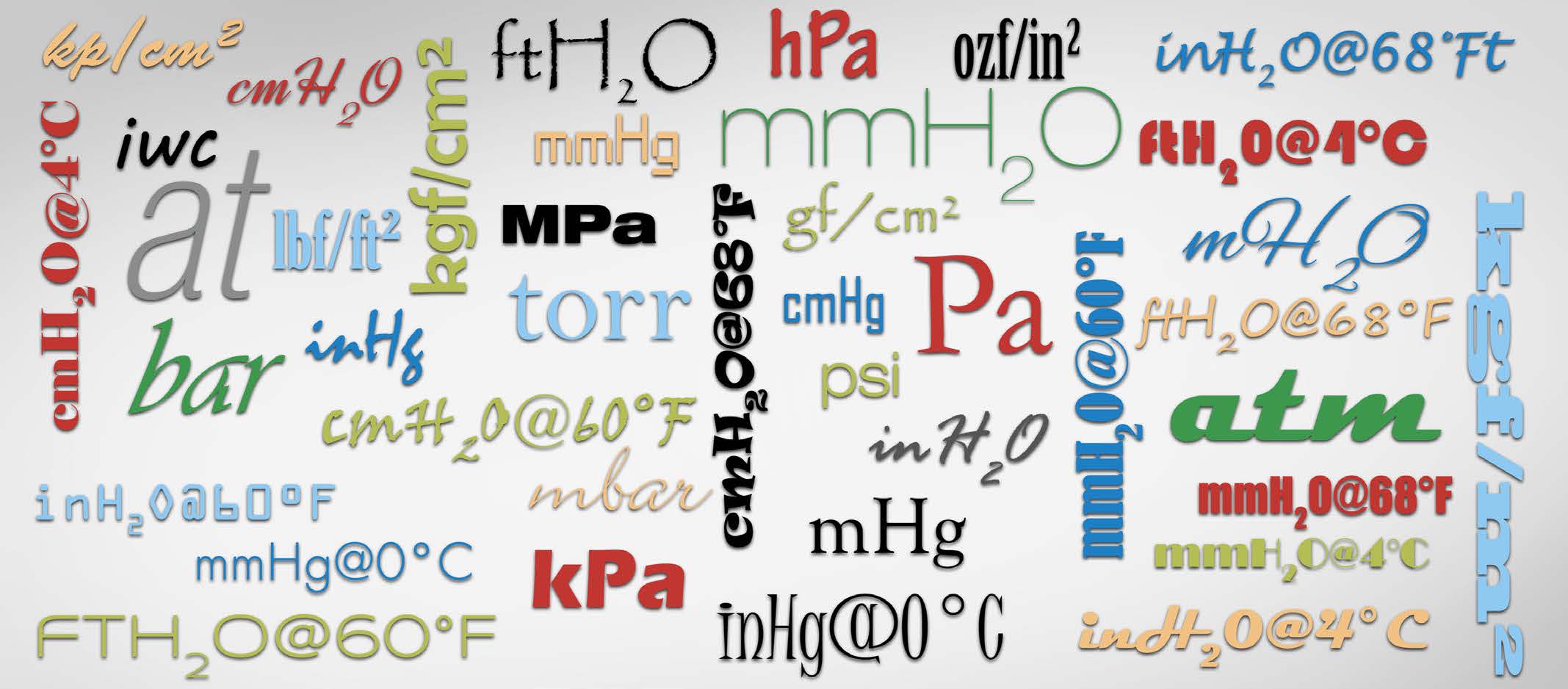
- Temperature units and temperature unit conversion
- Calibration video: How to calibrate a temperature measurement loop
- How to calibrate an RTD HART temperature transmitter
- Measurement Uncertainty: Calibration uncertainty for
dummies - Part 1
Beamex temperature calibration products
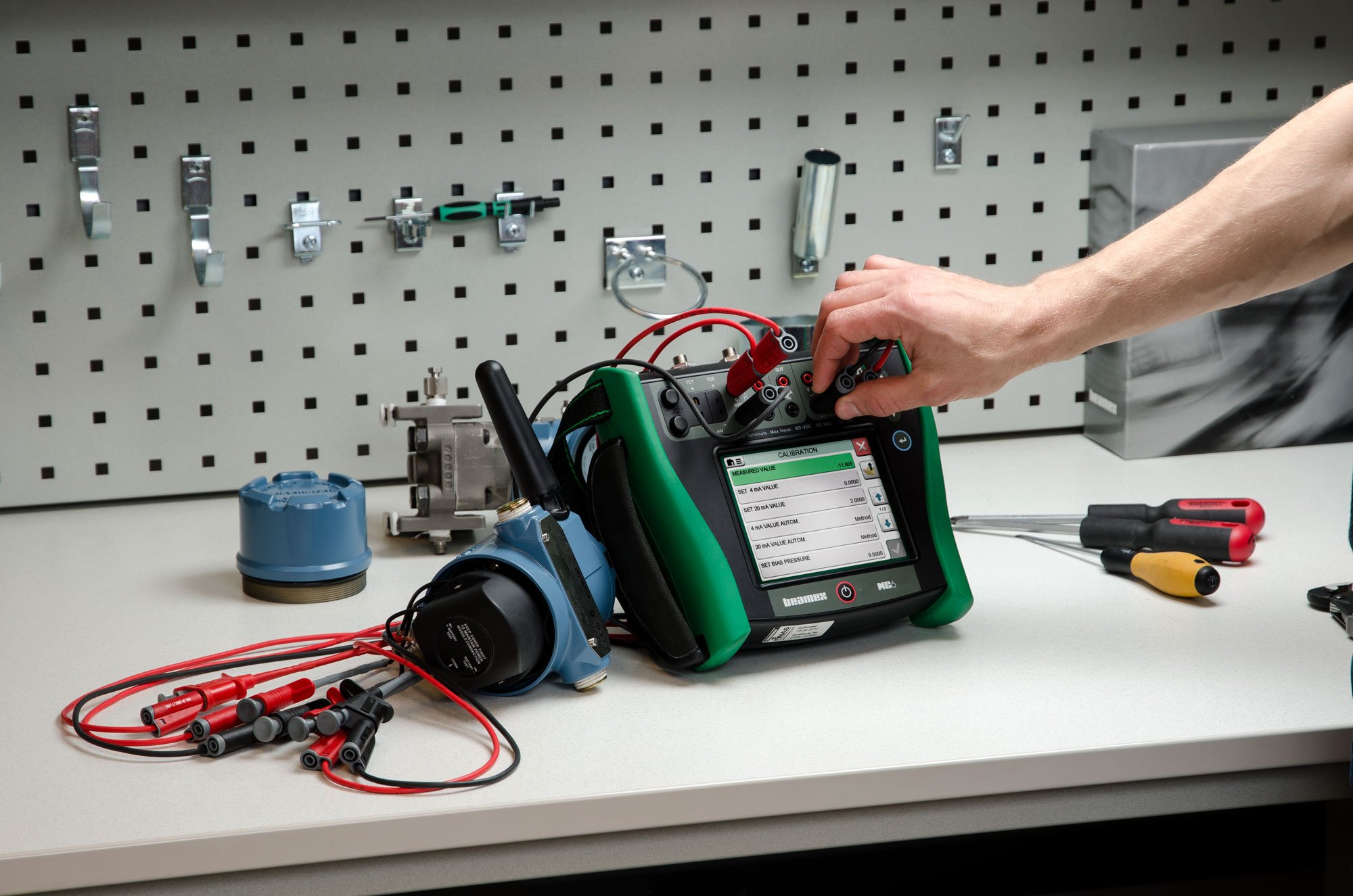
Please check out the new Beamex MC6-T temperature calibrator. A perfect tool for Pt100 sensor calibration and much, much more. Click the below picture to learn more:

Please check what other temperature calibration products Beamex offers, by clicking the below button:

Temperature Calibration eLearning
Free eLearning course on industrial temperature calibration.
Master temperature calibration with this free comprehensive eLearning course from Beamex. Deepen your knowledge, pass the quiz, and earn your certificate!
Temperature Sensor Calculator
A free tool to easily convert between temperature and electrical signals for thermocouples and RTD sensors.
https://www.beamex.com/resources/temperature-sensor-calculator/
Finally, please subscribe!
If you like these articles, please subscribe to this blog by entering your email address to the "Subscribe" box on the upper right-hand side of the page. You will be notified by email whenever new articles are available.


.png)


.jpg)

Discussion