In the previous blog post Ned discussed the basics of loop calibration.
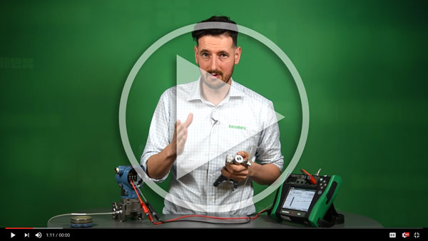
Now, let’s watch a video on the same subject.
In this video Roy shows an example of how to calibrate a temperature measurement loop. This loop consists of the following parts:
• Temperature sensor in the process
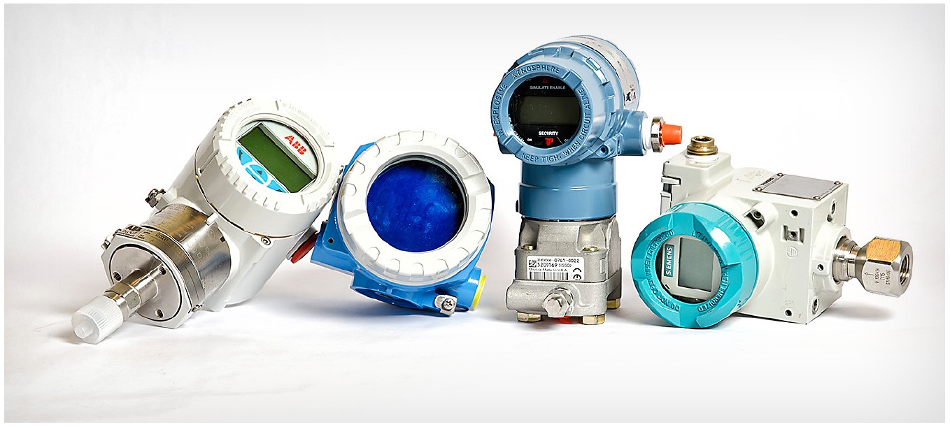
• Temperature transmitter in the field
• Local display in the field
• Control room display
In this example, the transmitter is a FOUNDATION Fieldbus transmitter, but it could also be a 4 to 20mA output analog transmitter. If using an analog transmitter, you would also have the DCS/PLC system input card as one part in the loop. As the FF transmitter has a digital output, there is no similar input card in the control system, which could affect the loop accuracy. So, you could say that the FF transmitter’s digital output is what is displayed in controls system, unless there is scaling done in control system.
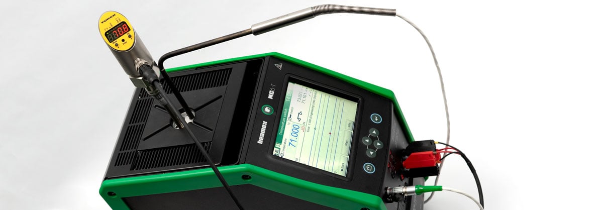
So, in order to calibrate the whole temperature loop, you start by injecting the process sensor into a temperature block that generates a known, accurate temperature. It is recommended that the temperature block have a reference temperature probe to assure best accuracy. Once each temperature set point is fully stabilized you will read the true temperature of the temperature block and call the control room to get the control room display. That way you will record the start and end points of the loop.
In this example Roy also reads the transmitter’s output and the local display in each temperature point.
Please take a look at the video below and make sure to also have a look at Ned’s previous blog post: Loop calibration basics for more details about loop calibration.






.jpg)

.png)
Discussion