
Temperature switches are commonly used in various industrial applications to control specific functions. As with any measuring instrument, they need to be calibrated regularly to ensure they are working accurately and reliably – lack of calibration, or inaccurate calibration, can have serious consequences. Calibrating a temperature switch is different from calibrating a temperature sensor or transmitter, for example, so this blog post aims to explain how to properly calibrate a temperature switch. Let’s start!
Table of contents
- How does a temperature switch work?
- The main principle of temperature switch calibration
- Essential terminology
- Is your temperature sensor separate or attached?
- How to calibrate temperature switches
- Temperature switch calibration steps – a summary
- Documenting calibration, metrological traceability, and calibration uncertainty
- Related blogs
- Beamex solution for temperature switch calibration
Before we go into details, here's a short video on this topic:
Download this article as a free pdf file by clicking the below image:

How does a temperature switch work?
In short, a temperature switch is an instrument that measures temperature and provides a required function (a switch opens or closes) at a programmed temperature.
One of the most common temperature switches is the thermostat switch in an electric radiator. You can set the thermostat to the required temperature and if the room is colder than the set temperature, the thermostat will switch the radiator on; if the room temperature is higher than required, the thermostat will switch the heating off.
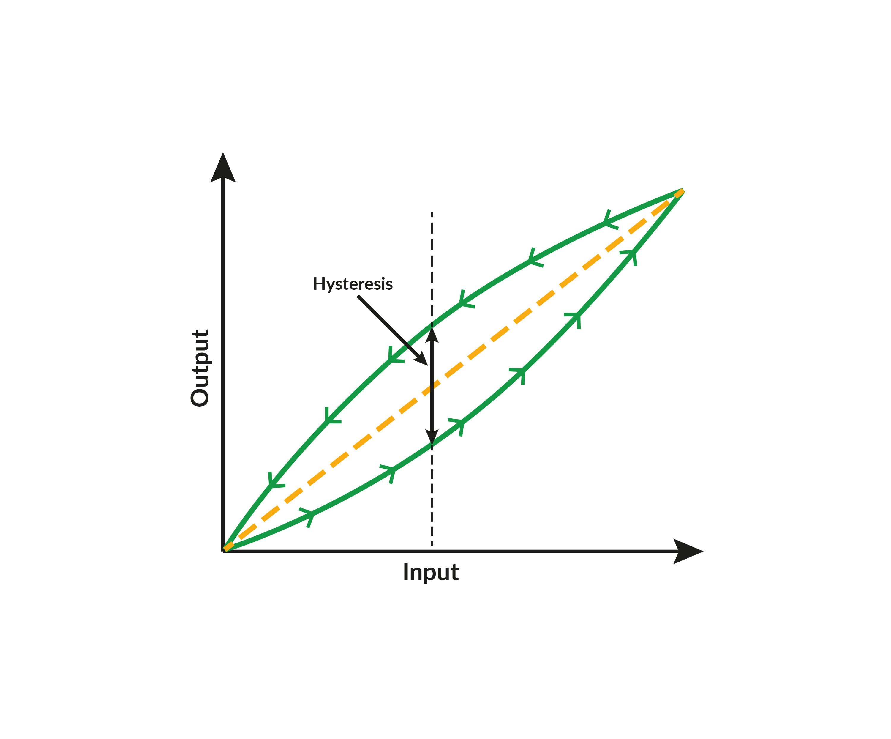
In practice, there is a small difference between the set and reset points so that the control does not start to oscillate when the temperature reaches the set point. This difference is called hysteresis, or deadband. In the above radiator example this means that when the thermostat is turned to 20 °C (68 °F), the radiator may start heating when the temperature is below 19 °C (66 °F) and stop heating when the temperature is 21 °C (70 °F), showing a 2 °C (4 °F) deadband.
Naturally, there are many different applications for temperature switches in industry.
The main principle of temperature switch calibration
We will investigate the details of temperature switch calibration later in this article, but to start, let’s briefly summarize the main principle to remember when calibrating a temperature switch:
To calibrate a temperature switch you need to slowly ramp the temperature at the switch input (the temperature-sensing element) while simultaneously measuring the switch output to see at which temperature it changes its state. Then you need to ramp the temperature back to find the “reset” point, where the switch reverts back to its original state.
When the output changes state, you need to record the input temperature at that exact moment.
The switch output usually only has two states, e.g. open or closed.
Essential terminology
One term commonly discussed is whether a switch type is normally open (NO) (or closing), or normally closed (NC) (or opening). This indicates if the switch contacts are open or closed by default. Usually temperature switches are in their default position when measuring the environmental temperature.
Operating points may also be referred to as Set and Reset points, or On and Off points.
The temperature difference between the operation points is called deadband. Some difference is needed between the closing/opening operating points to prevent the switch from potentially oscillating on and off if they work at exactly the same temperature. For applications that require a very small deadband, additional logic is provided to prevent the switch from oscillating.
The switch outputs may be mechanical (open/close), electronic, or digital.
Dry/wet switches are also sometimes discussed. Dry means that the output is closed or open, while wet means that there is a different voltage level representing the two switch states.
Some switches have mains voltage over the contacts when the switch is open. This can be a safety issue for both people and test equipment, so it should be taken into account when testing the switch.
A more detailed discussion on terminology can be found in this blog post:
Is your temperature sensor separate or attached?
As a temperature switch needs to measure temperature, it needs to have a temperature sensing element, in other words a temperature sensor.
In some cases the temperature sensor is a separate instrument and can be removed from the switch, while in others the sensor is fixed to the switch so they cannot be separated.
These two different scenarios require very different methods to calibrate the switch.
As explained above, you need to provide a slowly changing temperature for the switch input. This is very different depending on if the switch has a fixed temperature sensor or if the sensor can be removed.
Let’s look at these two different scenarios next.
#1 - Temperature switch with a separate/removable temperature sensor
In some cases, you can remove the temperature sensor from the temperature switch. The sensor will often be a common standard sensor, such as a Pt100 sensor (or a thermocouple). In these cases you can calibrate the switch without the temperature sensor by using a simulator or calibrator to simulate the Pt100 sensor signal, generating a slow temperature ramp (or a series of very small steps) as the input to the switch.
Naturally you also need to calibrate the temperature sensor, but that can be calibrated using normal temperature sensor calibration at fixed temperature set points, without needing to slowly ramp the temperature, which makes the sensor calibration much easier (and with less uncertainty).
In accurate applications, the switch may be compensating for RTD sensor error by using correction coefficients, such as ITS-90 or Callendar van Dusen, so when simulating the temperature sensor your sensor simulator should be able to take this into account.
Find out more on temperature sensor calibration in this earlier post: how to calibrate temperature sensors.
You can calibrate the sensor and switch together as a loop; you don’t have to calibrate them separately. But if you don’t have a system that generates a slow, controlled temperature ramp, it is easier to calibrate them separately.
If the removable temperature sensor is a not a standard sensor type (neither an RTD nor a thermocouple), then you can’t really calibrate the sensor and switch separately as you can neither measure nor simulate the signal of the non-standard sensor. In that case you need to calibrate them as one instrument when they are connected.
#2 - Temperature switch with an integrated/fixed temperature sensor
If your temperature sensor is fixed to your temperature switch and cannot be removed, you need to calibrate it all as one instrument. In that case you need to generate a temperature ramp with a temperature source that you insert the temperature sensor into.
How to calibrate temperature switches
Before calibration
As with any process instrument calibration, before starting, isolate the measurement from the process, communicate with the control room, and make sure the calibration will not cause any alarms or unwanted consequences.
Visually check the switch to ensure it is not damaged and all connections look ok.
If the sensor is dirty, it should be cleaned before inserting it into the temperature block.
Generate a slow temperature ramp as input
If you are calibrating the temperature switch and its temperature sensor together, you need to generate a slow enough temperature ramp in the temperature source where you install the switch's temperature sensor.
This means you need to have a temperature source that can generate a controlled temperature ramp at a constant speed, as slow as the application requires.
In practice you can quickly reach a temperature set point close to the calibration range, let the temperature fully stabilize, and then start slowly ramping the temperature across the calibration range. After the calibration you can quickly return back to room temperature.
A temperature ramp like this is most commonly generated with a temperature dry block. Not all dry blocks are able to generate a suitably slow ramp. And you also need to be able to measure the generated temperature very accurately, while at the same time being able to measure the switch output signal. In addition, the calibration system should have the capability to automatically capture the input temperature at the exact moment when the switch output changes its state.
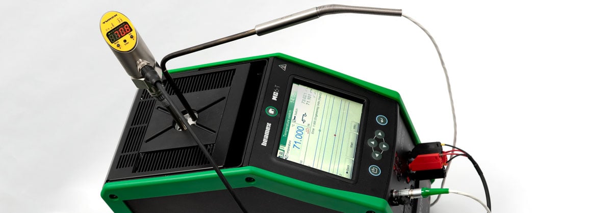
Not all temperature calibration systems can do all this, but needless to say, the Beamex MC6-T temperature calibrator can do it all fully automatically. And not only that, it can do many other things too, so please make sure you check it out!
Use an external reference temperature sensor – don’t use the internal one!
Temperature dry blocks always have an internal reference sensor, but do not use this when calibrating temperature switches!
The internal reference sensor is located in the bottom part of the temperature block, which is heated and/or cooled. The internal reference sensor is also usually close to the heating/cooling elements and responds quickly to any temperature changes.
From that temperature block, the temperature will transfer to the insert and from the insert it will transfer to the actual temperature sensor. This means that there is always a significant delay (lag) between the internal reference sensor and the sensor being calibrated, located in the hole in the insert.
In a normal sensor calibration, done at fixed temperature points, this delay is not so critical, because you can wait for the temperatures to stabilize. But for temperature switch calibration this delay has a huge impact and will cause significant error in the calibration result!
Instead of using the internal reference sensor, you should use an external reference sensor that is installed in the insert together with the switch’s sensor to be calibrated. The external reference sensor should have similar characteristics to the temperature switch sensor in order for them to behave the same way, with a similar lag.
At the very least make sure that the dimensions of the reference sensor and temperature switch sensor are as similar as possible (e.g. similar length and diameter). Ensuring that the sensors have the same length means they will go equally deep into the insert, with the same immersion depth. Different immersion depths will cause error and uncertainty in the calibration.
Naturally the reference temperature sensor also needs to be measured with an accurate measurement device.
Measuring the switch output
Once you have the input temperature ramp figured out, you also need to measure the switch output terminals and their state.
With a traditional open/close switch, you need to have a device that can measure if the switch contacts are open or closed.
If the switch is more modern with an electrical output, you need to be able to measure that. That may be current measurement for an mA signal, or voltage measurement for a voltage signal.
Anyhow, as the switch output has two states, you need to have a device that can measure and recognize both.
Capturing the operation points
To calibrate manually you need to start the temperature ramp and monitor the switch output. When the switch’s status changes, you need to read what the input temperature is, i.e. what the reference temperature sensor is reading. That is the operating point of the temperature switch. Usually you want to calibrate both operation points (the “set” and “reset” points) with increasing and decreasing temperatures to see the difference between them, which is the hysteresis (deadband).
If you don’t want to do that manually, then you need a system that can perform all of the required functions automatically, i.e. it needs to:
- Generate the temperature ramp, going up and down at the required speed, within the required temperature range for the switch in question
- Measure the switch’s output state (open/close, on/off)
- Measure the reference temperature sensor inserted in the temperature source
- Capture the temperature when the switch changes state
The Beamex MC6-T can do all of this and much more.
Temperature switch calibration steps – a summary
Let’s finish with a short summary of the steps needed to calibrate a temperature switch:
- Pre-calibration preparation (disconnect from process, isolate for safety, visual check, cleaning).
- Insert the temperature switch’s temperature sensor and a reference sensor into the temperature source.
- Connect the switch’s output to a measurement device that measures the switch’s open/close status.
- Quickly ramp the temperature close to the switch’s operation range and wait for it to stabilize.
- Very slowly ramp the temperature across the switch’s nominal operation range.
- When the switch output changes status (set point), capture the temperature in the temperature source.
- Slowly ramp the temperature in the other direction until the switch operates again (reset point). Capture the temperature.
- Repeat steps 5 to 7 as many times as needed to find the repeatability of the switch. Typical practice is three (3) repeats.
- Ramp the temperature quickly back to room temperature.
- Document the results of the calibration.
- If the calibration failed and the switch did not meet the accuracy requirements, make the necessary adjustments, repair, or replace it.
- Repeat the whole calibration process if adjustments were made in step
- Connect the switch back to the process.
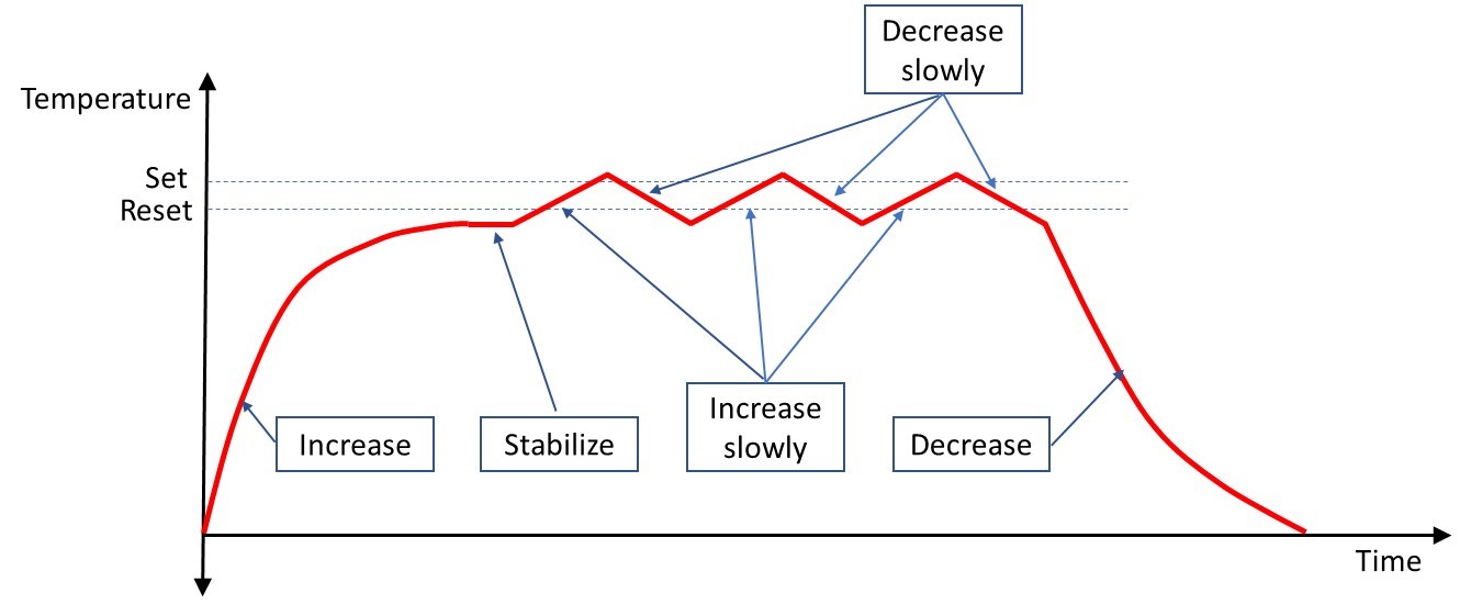
The above graph illustrates an example temperature cycle during temperature switch calibration. In the beginning you can quickly reach a temperature point close to the calibration range, let the temperature fully stabilize, and then start slowly ramping the temperature up and down across the calibration range to capture the set and reset points. In this example three calibration repeats were done to record the repeatability of the switch. After calibration you can quickly decrease the temperature back to room temperature.
Documenting calibration, metrological traceability, and calibration uncertainty
A few important reminders about temperature switch calibration, or indeed any calibration:
Documentation – calibration should always be documented; typically this is done with a calibration certificate.
Metrological traceability – calibration equipment should have valid metrological traceability to relevant standards.
For more information on metrological traceability, check out this blog post:
Metrological traceability in calibration - are you traceable?
Calibration uncertainty – calibration uncertainty is a vital part of every calibration process. You should be aware of how “good” your calibration process and the calibration equipment are, and if the process and equipment provides low enough uncertainty for the calibration in question.
For more information on calibration uncertainty, please check this blog post:
Calibration uncertainty for dummies
Related blogs
If you found this post interesting, you might also like these blog posts:
- Temperature Calibration [eBook]
- How to calibrate temperature sensors
- Temperature Calibration Webinars
- Pressure Switch Calibration
Beamex solution for temperature switch calibration
Beamex provides a fully automatic system for temperature switch calibration. The heart of the solution is the Beamex MC6-T temperature calibrator. The MC6-T is an accurate and versatile temperature calibrator with built-in multifunction process calibrator and communicator technology.
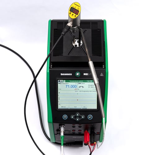
With the MC6-T you can create the required temperature ramp, measure the switch output, measure the reference temperature sensor, and capture the operation points. And all of this can be done fully automatically. The calibration results are stored in the MC6-T’s memory, from where the results can be uploaded to Beamex CMX or LOGiCAL calibration software, for storing results in databases and generating calibration certificates. The whole calibration process is automatic and paperless.
Please feel free to contact us to learn more about the MC6-T or to book a free physical or virtual online demonstration:


.png)


.jpg)


Discussion