 Junction Compensation - Beamex blog post")
In this blog post, I will take a short look on thermocouples and especially on the cold junction and the different cold junction compensation methods.
During the many years of working with process instrument calibration, it often surprises me that even people who work a lot with thermocouples don’t always realize how the thermocouples, and especially the cold (reference) junction, works and therefore they can make errors in measurement and calibration.
To be able to discuss the cold junction, we need to take first a short look into the thermocouple theory and how a thermocouple works.
I won’t go very deep in the theoretical science but will stick more with practical considerations, the kind of things you should know when you work with thermocouple measurements and calibrations in a typical process plant.
Download this article for free as pdf file:

Terminology: Cold junction or Reference junction
Thermocouple “cold junction” is often referred to as a “reference junction”, but it seems to me that people use “cold junction” more often, so I will use that one in this text.
Thermocouples
Thermocouples are very common temperature sensors in process plants. Thermocouples have few benefits that makes them widely used. They can be used to measure very high temperatures, much higher than with RTDs (Resistance temperature detector). The thermocouple is also a very robust sensor, so it does not break easily. Although thermocouples are not as accurate as RTD sensors, they are accurate enough in many applications. Thermocouples are also relatively cheap sensors and the thermocouple measurement circuit does not require excitation current like an RTD circuit does, so the circuit is in that sense, more simple to make. There are many different thermocouple types optimized for different applications.
A thermocouple sensor seems very simple to use – just two wires – what could possibly go wrong?
But considering the cold junction, and all the junctions in the measurement circuit, it is not always as simple as it seems.
Let’s start working our way towards the cold junction discussion, but before that, a few more words on the thermocouple theory to help better understand the cold junction discussion.
How does a thermocouple work?
Let’s look at how a thermocouple works. A thermocouple consists of two wires made of different electrical conductors that are connected together at one end (the “hot” end), that is the end you want to use to measure the temperature with.
As discovered back in 1821 by Thomas Johann Seebeck, when the connection point of these wires is taken into different temperatures, there will be a thermo-electric current generated, causing a small voltage between the wires in the open end. The voltage depends on temperature and on the materials of the conductive wires being used. This effect was named as Seebeck effect.
Simplified principle picture of a thermocouple:
 Junction Compensation - Beamex blog post")
In the above picture: the “Thermocouple material 1 and 2” represent the two different materials the thermocouple is made of. “T1” is the hot end of the thermocouple, i.e. the point that is used to measure temperature. The two “Tcj” are the temperatures of the cold junctions.
The above explanation is somewhat simplified, as the thermovoltage is actually generated by the temperature gradients in the thermocouple wire, all the way between the “hot” and “cold” junctions. So, it is not the junction points that actually generate the voltage, but the temperature gradient along the wire. It is easier to understand this by thinking that the thermovoltage is generated in the junctions, hot and cold ones. Maybe more scientific thermocouple theory can be provided in some other post later on, but in this one, let’s stick with the practical considerations.
Thermocouple types and materials
There are many types of thermocouples being manufactured from different materials and alloys. Different materials will cause different sensitivity, different amount of thermovoltage being generated at the same temperature, and will affect other characteristics such as max temperature.
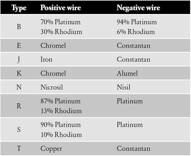
Several various thermocouple types have been standardized and names are given for specified materials being used. Names are typically very short names, often just one letter, such as type K, R, S, J, K, etc.
Some of the most common thermocouples and their materials are listed in the below table:
Wire colors
Good news is that the thermocouple wires are color coded for easier recognition.
Bad news is that there are many different standards for the color codes and they differ from each other.
The main standards are the IEC60584-3 (International) and ANSI (United States), but there are also many others, such as Japanese, French, British, Netherland, German, etc. standards. So unfortunately, it is a bit complicated to recognize the type by the color.
Thermocouple’s thermovoltage
As different thermocouples are made of different materials, the thermovoltage is also different, this is illustrated in below picture. There is a big difference in the voltage being generated in the same temperature between the different types.
 Junction Compensation - Beamex blog post")
If you want to measure a lower temperature, it is obviously better to use the more sensitive types as they give a higher voltage which is easier to measure. But if you need to go to high temperatures, you need to choose some of the less sensitive types that can be used in such high temperatures.
The Seebeck coefficient tells how much the thermocouple’s voltage changes compared to a change in temperature. More on that later.
The above picture illustrating the different sensitivities between different thermocouples also explains why a thermocouple calibrator typically has different accuracy specifications for different thermocouple types. A measurement device, or calibrator, normally has the voltage measurement accuracy specified in voltage. For example, it can have an accuracy of 4 microvolts. This 4 microvolt accuracy equals a different temperature accuracy depending on the thermocouple type, due to the different thermocouple sensitivities.
Measurement device (calibrator) example
Let’s look at the two extremities: the E and B type at 200 °C temperature. The sensitivity (Seebeck coefficient) of type E at 200 °C is about 74 µV/ °C, while the coefficient for B type at 200 °C is about 2 µV/ °C. So, there is a difference of 37 times between these two.
For example, if your measurement device can measure with an electrical accuracy of 4 µV, that means that it offers accuracy of about 0.05°C (4 µV divided by 74 µV/°C) for the E type at 200°C, and accuracy of 2°C (4 µV divided by 2 µV/°C) with B type at 200°C.
So, we can see why there are often very different accuracy specifications for a thermocouple measurement device/calibrator for different thermocouple types.
Calibrator accuracy
If you see a data sheet of a temperature calibrator and it has the same accuracy specification for all thermocouple types, be careful! Normally this means that the specifications / data sheet has been done in the marketing department and not in the technical department… ;-)
This is just not very realistic.
Standards
There are also some standards (for example AMS2750E) that require the same accuracy for all thermocouple types, and this does not make very much sense in practice, due to this huge difference in sensitivity with different types.
Seebeck coefficients
I already mentioned the Seebeck coefficient earlier. This is the sensitivity of the thermocouple, i.e. it explains how much voltage is generated per temperature change.
The below picture shows Seebeck coefficients for some different thermocouples:
 Junction Compensation - Beamex blog post")
Cold junction
Now, lets start diving into the "cold junction"...
Earlier, I showed the picture of the simplified thermocouple principle showing that the thermovoltage is generated in the “hot” end connection, where the two different conductors are connected together. The big question you should be asking here is: But what about the other end of the wires?
What a good question! I’m glad you asked… ;-)
When you measure the voltage of the thermocouple, you could connect the thermocouple wires into a multimeter, simple right? Not really! The multimeter connection material is typically copper or gold plated, so it is a different material than the thermocouple material, meaning you create two new thermocouples in the multimeter connections!
Let’s illustrate that with a picture:
 Junction Compensation - Beamex blog post")
In the above picture, the material 1 and material 2 are the two thermocouple materials that form the thermocouple. The “hot end” is the point where they are welded together and that is the point that measures process temperature, this is where the voltage U1 is generated. This U1 is what we want to measure. In the “cold junction” points, the thermocouple is connected to the voltage meter that has connections made of different material, material 3. In these connections, thermovoltage U2 and U3 are being generated. It is these U2 and U3 voltages that we do not want to measure so we want to get rid of these or to compensate them.
As we can see in the above picture, you are actually measuring the voltage of three (3) thermocouples connected in series. You would obviously like to measure only the voltage / temperature of the “hot” junction only and not the other two junctions.
So, what can you do?
You need to somehow eliminate or compensate for the thermocouples created in the cold junctions. There are different ways to do that. Let’s look at those next.
Cold junction options and compensation methods
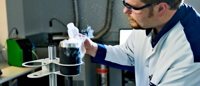
1. Cold junction in ice-bath
The connections need to be electrically isolated from the water in the ice-bath to avoid any leak currents causing errors, or possible corrosion being generated.
This is a very accurate way and it’s something calibration laboratories typically do. It is anyhow not very practical on a process plant floor, so it is not normally used in process plants.
 Junction Compensation - Beamex blog post")
Example:
Type N thermocouple is connected as presented in the picture. Voltage meter shows 20808 µV. What is the measured temperature?
E = EN(tU1) – EN(tr)
Where:
- E = measured voltage = 20808 µV
- EN(tU1) = voltage generated in hot junction
- EN(tr) = voltage generated in the cold (reference) junction = 0 µV (IEC 60584 type N, 0 °C)
- EN(tU1) = E + EN(tr) = 20808 µV + 0 µV = 20808 µV = 605 °C (IEC 60584 type N, 20808 µV)
So, the temperature is 605 °C.
2. Cold junction in a known, fixed temperature
Since the ice-bath was found to be impractical, you can also do the cold junction connection in some other known, fixed temperature. You can have a small connection box that has a temperature control keeping the box always at a certain temperature. Typically, the temperature is higher than environment temperature, so the box needs only heating, not cooling.
When you know the temperature that your cold junction is in, and you also know the type of your thermocouple, you can calculate and compensate the cold junction thermovoltage.
Many measurement devices or temperature calibrators have a functionality where you can enter the temperature of the cold junction and the device will do all the calculations for you and make the compensation.
 Junction Compensation - Beamex blog post")
Example:
Type N thermocouple is connected as presented in the picture. Voltage meter shows 19880 µV. The temperature of the cold (reference) junction is 35 °C. What is the measured temperature?
E = EN(tU1) – EN(tr)
Where:
- E = measured voltage = 19880 µV
- EN(tU1) = voltage generated by the hot end
- EN(tr) = voltage generated in reference (or cold) junction = 928 µV (IEC 60584 type N, 35 °C)
- EN(tU1) = E + EN(tr) = 19880 µV + 928 µV = 20808 µV = 605 °C (IEC 60584 type N, 20808 µV)
So, the measured temperature is 605 °C.
Please note that thermocouple calculations must always be made in voltage. A common error is to look for the table value for the measured voltage and add the cold junction temperature. In this case, the corresponding temperature for the measured 19880 µV according to IEC 60584 standard is 581.2 °C. Calculation using temperature values would give 581.2 °C + 35 °C = 616.2 °C. The error is + 11.2 °C.
3. Measure the temperature of the cold junction
If you don’t adjust the cold junction temperature like in the previous example, you can anyhow measure the temperature of the cold junction with a temperature probe. You can then compensate the cold junction effect, but the compensation is a little bit more difficult as you need to measure the cold junction temperature all the time, and knowing your thermocouple type, make calculations to know the effect of the cold junction.
Luckily, many temperature calibrators provide a functionality to use a temperature probe to measure the cold junction temperature and the device makes all the compensations and calculations automatically.
 Junction Compensation - Beamex blog post")
4. Automatic on-line compensation in the measuring device
I mentioned that the previous example was difficult as you need to calculate the compensation at all times, but you could leave that to the measuring device to do it automatically. The measuring device (being a transmitter, DCS input card or temperature calibrator) can be measuring the temperature of the cold junction all the time and automatically perform an on-line compensation of the cold junction error. Since the measuring device also knows the thermocouple type (you select that in the menu), it can make the compensation automatically and continuously.
This is naturally the easiest and most practical way to compensate the cold junction in normal measurements and calibrations, as you don’t need to worry about the cold junction and leave for the equipment to take care of. You just plug in the thermocouple wire into the device.
The Beamex temperature calibrators are also supporting this kind of automatic compensation.
 Junction Compensation - Beamex blog post")
Download free white paper
Download this article for free as pdf file:
Related Beamex products
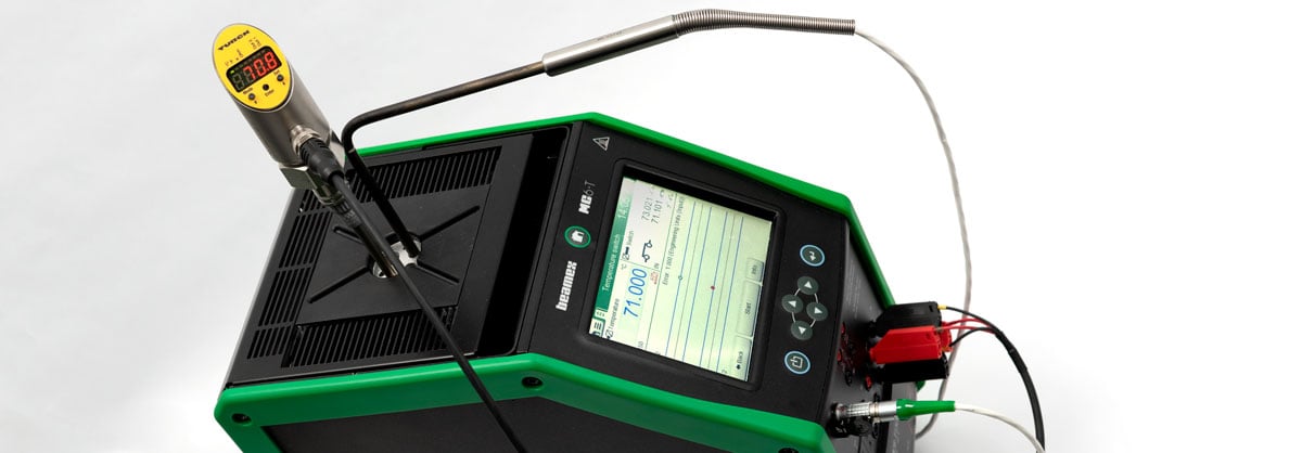
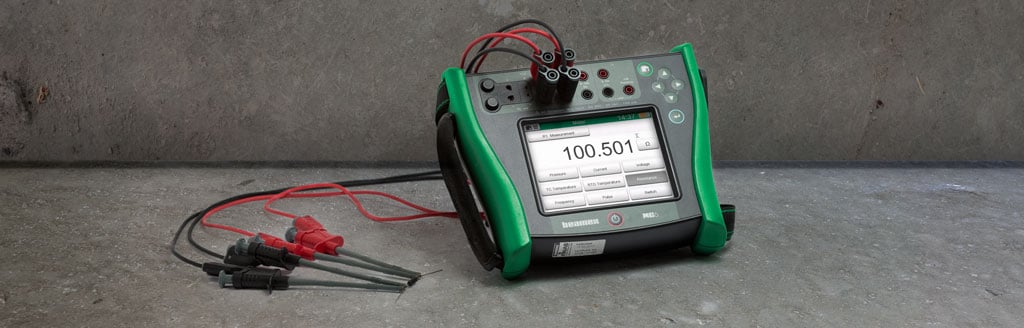
Please take a look at the Beamex MC6-T temperature calibrator. It can be used also for calibrating thermocouples and it has an automatic cold junction compensation. It also offers a versatile connector where you can connect different thermocouple connectors, or bare thermocouple wires.
Click the below picture to learn more about Beamex MC6-T:

Also, take a look at the Beamex MC6 calibrator for reference.
Temperature Calibration eLearning
Free eLearning course on industrial temperature calibration.
Master temperature calibration with this free comprehensive eLearning course from Beamex. Deepen your knowledge, pass the quiz, and earn your certificate!
Temperature Sensor Calculator
A free tool to easily convert between temperature and electrical signals for thermocouples and RTD sensors.
https://www.beamex.com/resources/temperature-sensor-calculator/

.png)


.jpg)


Discussion