
In this blog post, I explain how a resistance or RTD meter works and the difference between the 2, 3, and 4 wire connections.
Maybe you know that in resistance and RTD (Resistance Temperature Detector) measurement you can use 2, 3 or 4 wires, but maybe you don’t really remember what the difference is between them, or how these connections really work. It’s embarrassing to admit that, I know. But don’t worry - I will explain how these things work. Read this and then you will know. We don’t have to tell anybody that you learned it from me, let’s keep that between us... ;-)
In this blog post, I explain shortly & simply how a resistance or RTD meter works and the difference between the 2, 3, and 4 wire connections. I hope this info helps you in practice in your job.
Download this article as pdf file >>
Let’s start digging – how does a resistance/RTD meter work?
Let’s start building this from the foundation up. Before talking about the number of wires, let’s first look at how a resistance meter works.
To begin: a resistance meter does not actually directly measure resistance. What?
The way a resistance meter normally works is by sending a small, accurate current through the resistance to be measured and then it measures the voltage drop formed over the resistance. After it knows the current and voltage, our good old friend, Ohm’s law, solves the rest. Ohm’s law says that resistance is voltage divided by current, or R = U/I.
For example, if there is a 1 mA (0.001 A) current going through a resistor and there is a voltage drop of 0.100 V over the resistor, then the resistor is R=U/I = 0.100 V / 0.001 A = 100 ohm.
So, the resistance meter actually measures the resistance via the current and voltage measurement.
Typically, the measurement current is around 1 mA, so if you are measuring a resistance of 100 ohms, there will be a 0.1 V voltage-drop over the resistance. The higher resistance ranges will use smaller measurement currents. Often, temperature transmitters use a current of about 0.2 mA. I’ve seen transmitters with current from 0.1 mA up to several mA. And the current is not always a DC current, but it can be pulsed.
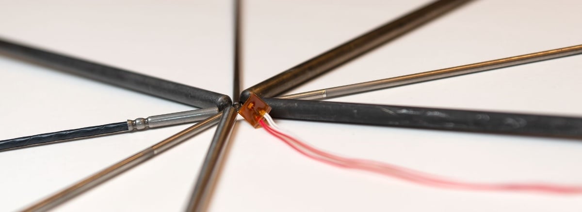
The measurement current will cause self-heating in an RTD probe, due to power dissipation, especially in small RTD elements that have a poor thermal connection with its surroundings. Therefore, the measurement current should be kept low. More on RTD probes in another post…
The resistance measurement device itself must of course know exactly what current it is using to make the calculation correctly.
Maybe it is time for a diagram to explain this:

In the above picture, the box “Resistance meter” corresponds a resistance (or RTD ) meter. The two black dots and the connections, and the “R” is the resistance you want to measure.
The above picture is using a 2-wire connection, as there are only two wires (test leads) being used to connect the resistance. In the above picture, the wires are ideal with no resistance in them. But in practice, all wires and test leads have some resistance and the contacts will always have resistance too.
So, if we illustrate a practical two-wire connection considering the resistance of the wires and connections (Rw), we get the following practical schematic below:

In practice, the big problem here is that the resistance meter will now measure the total resistance being a combination (series connection) of the “resistance to be measured” and all the resistance in the wires and connections.
What the meter sees is the sum of Uw + Ur + Uw, although it would like to see only the Ur. As the result of this, the resistance meter indicates a resistance that is a combination of the R and all the connection resistances.
Therefore, there is an error in the result.
The measurement is always too high. Depending on the wires & connections, this can cause a huge error in the measurement. In the case of long wires and poor connections, the error can be several ohms (or even infinite). But even when using high-quality test leads and clips, there will always be some error.
If you want to make reliable and accurate resistance (or RTD) measurements, never use a 2-wire connection.
How do you get rid of these errors from a 2-wire measurement?
The best answer is to use a 4-wire connection. Let's look at that next.
4-wire resistance measurement
With the 4-wire connection, the idea is to have separate wires to deliver the measurement current and to measure the voltage drop over the resistance.
For this kind of connection, 4 wires are needed, leading to the name. Pretty logical…
Let’s look at a picture to illustrate a 4-wire connection:

You may wonder, “what difference does this make compared to a 2-wire connection?” Well, it would not make any difference with ideal wires and connections, but it’s pretty difficult (impossible) to get ideal wires in real world. So, in practice, with all the unknown varying resistances in the wires and connections, this will make all the difference.
Why is that? Well, that’s what I’m here for:
There are now separate dedicated wires that will deliver the accurate current through the resistance. If there is some resistance in these wires and connections, it does not matter, because the fixed current generator will still generate the same accurate current and the current does not change as it passes through these connection resistances.
Also, there are separate wires for the voltage measurement which are connected directly to the legs of the resistance to be measured. Any resistance in these voltage measurement wires does not have any effect on the voltage measurement because it is a very high impedance measurement. There is practically no current in these wires and even though there would be resistance, it does not cause any voltage drop, so there is no error.
As a result of the above, the 4-wire connection can measure the connected resistance (R) accurately, even there would be resistance in all the connection wires and connections.
Therefore, 4-wire connection is the best and most accurate way to measure resistance or RTD sensor.
A practical schematic of the 4-wire measurement diagram from earlier would look something like the below picture, with wire and connection resistances (Rw) added:

3-wire resistance measurement
In practice, having to use/install 4 wires can be a bit time consuming/expensive. There is a simplified modification of the 4-wire connection, which is a 3-wire connection. Yep, you guessed right, it uses 3 wires.
Although the 3-wire connection is not quite as accurate as the 4-wire one, it is very close if all 3 wires are similar and it is far better than the poor 2-wire connection. Therefore, the 3-wire connection has become the standard in many industrial applications.
In a 3-wire connection, the idea is that we remove one of the wires and assume that all the wires are similar in resistance.
Now, let’s look at the schematics of a 3-wire connection, with wire resistances included:

In the above schematic, the lower part has only one wire. So, the lower part connection reminds us of the 2-wire connection, while the higher connection is like the 4-wire connection. In the higher part, the meter can compensate for the wire resistance, like in 4-wire connection. But in the lower part, it has no means to compensate for the wire (Rw3) resistance.
So, how does the connection work?
The resistance meter has internal switching, so it can first measure just the resistance of the upper loop (summary of Rw1+Rw2), then it divides that result by 2 and gets the average resistance of these two wires. The meter then assumes that the third wire (Rw3) has the same resistance as the average of Rw1 and Rw2. Then it switches to a normal connection (as shown in the picture) to measure the connected impedance R, and it uses the results of the earlier measured wires resistance in the measurement result.
It’s good to remember, that the 3-wire connection is accurate only if all the 3 wires and connections have the same resistance. If there are differences in the wire and connection resistances, then the 3-wire connection will result in an erroneous measurement result. The error in 3 wire measurement can be either way (too high or too low) depending on the resistance difference between the cables and connections.
In industrial applications, the 3-wire connection is often a good compromise; it is accurate enough and you need to use one less wire than with the perfect 4-wire measurement.
Conclusion
A few things to remember:
- When calibrating the resistance of an RTD, use a 4-wire connection, if possible.
- Of course, when you calibrate an RTD temperature transmitter that is configured for 3-wire measurement, you need to use 3 wires. Make sure you use 3 similar wires and that you make good contacts.
- When using a 3-wire RTD probe in process, connected to an RTD transmitter, make sure you make good contacts to the transmitter screws for all 3 wires.
- When using a RTD reference probe in calibration, make sure you always use a 4-wire connection.
- Never use 2-wire resistance measurement for anything that you need to be accurate. Sure, it can be used for troubleshooting and for rough measurements.
I hope you found some of this post useful.
As always, please comment and send us ideas for good calibration related topics that you would like to read about in this blog in the future.
Download this article
Download this article as a pdf file by clicking the picture below:
And finally…
Ooops, I forgot to mention Beamex. Please go and buy some Beamex stuff right now! … ;-)

Thanks,
Heikki


.jpg)


Discussion