
If I had to summarize the content of this post into one sentence, it would be:
Using a mA meter with an internal impedance that is too high to measure current over the transmitter’s test connection will result in erroneous measurement results!
Lately, I have seen several people who have made this mistake, so I decided to write a short blog post on it. Hopefully, it will save some of you from making the same mistake.
The main point is that it is pretty easy to have erroneous mA measurement results when you are measuring the transmitter current through the test connection. The dangerous part is that you won’t necessarily even realize it.
Let’s take a look at what the mistake is and how to avoid it.
I also want you to understand how this system works, therefore some background information and educational theory behind it is in place.
Ready? Let’s go….
Transmitter’s test connection
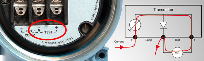
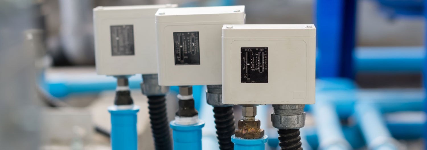
Many process transmitters, specifically pressure transmitters, have a “test connection” in the connection panel. It is typically marked with “TEST” text and it is located next to the normal mA loop connections.
I’m sure you have seen it; in one transmitter, it looks like this:

Purpose of the test connection
The purpose of the test connection is to be able to easily measure the loop current going through the transmitter, without the need to disconnect wires or break the current loop. You just connect your mA meter to the TEST connection and you can see the current that is going through the transmitter, as all the current now goes through your current meter.
When you disconnect your current meter, all the current starts to again go through the internal diode (I will explain diodes soon) in the test connection. At any point, there is no cut in the current loop.
Schematics
As engineers, we just love schematic diagrams, so I need to add some here also.
In the transmitter, there is a diode inside the transmitter connected between the test connections. One end of the diode is connected to one of the “loop” connections, and other end of the diode connected to the test connection. Sounds complicated when you read it, but it is very simple. I’m sure a picture will help you to understand this…
With a schematic diagram, it typically looks like this:

What is a diode and does it work?
To better understand this phenomenon, we need to look at what a diode is and how it works.
A diode is a small electronic semiconductor component made with P and N materials. Most electronic devices have many diodes inside, even calibrators… ;-)
An ideal diode will conduct DC current only in one direction. An ideal diode would always conduct current when the voltage over the diode is the right way around. In practice, it is a bit more complicated and the diodes are not ideal.
Here’s characteristics of an ideal diode (left) and a realistic diode (right):


As we can see in the characteristics of a diode (the real one, not the ideal one), the forward current starts flow when the voltage over the diode is large enough and exceeds the threshold voltage. Typically, with a silicon diode the threshold voltage is about 0.6 V. When the voltage is more than this threshold, the diode is “open” and the current goes through it. When the voltage is less than the threshold, the diode is “closed” and no current goes through it.
Current through a transmitter
In normal use of a transmitter, the loop supply effects the diode, so the diode is fully open and all loop current goes through the diode. So actually, the diode doesn’t really do anything, it is not even needed in normal operation and could be replaced with a short-circuit.
But when you connect an mA meter over the diode, all the current starts to go through the mA meter and none of it goes through the diode anymore. Magic!? Well, no magic, just electronics.
Pictures below show how the current goes through test diode (above) or mA meter (below):


Well, this is how it should work, but it does not always work like that in practice. Read on…
How does an mA meter work?
Why am I talking about impedance of a mA meter? What is that impedance?
The way mA meters are normally built, there is an accurate shunt resistor, a few ohms, that the current goes through (R in the picture below). This current causes a voltage drop over the shunt resistor and by measuring this voltage with an A/D converter (V in the picture) we can calculate the current.
The rest is simple mathematics, per the Ohm’s law: I = U/R (Current = Voltage / Resistance).

Unfortunately, some mA meters/calibrators have impedance that is a bit too high, which causes the voltage drop over the resistor to be larger. In most applications, larger impedance is not critical, but with the transmitter’s test connection it is. When the voltage drop becomes larger it causes the test diode to start opening either slightly causing small leakage current, or all the way open.
Why would you put higher impedance in a mA meter? It may be easier to design a mA meter using a bit higher impedance, as then the voltage drop becomes higher and it is easier to measure it internally with A/D converter, since the voltage signal is higher.
For example, if the internal impedance of an mA meter would be as high as 50 ohms, then with a 20 mA current this means that the voltage drop over the mA meter (and test connection’s diode) would be 1 V causing the test diode to be fully open (threshold 0.6 V). This would mean that your mA meter would show hardly any current, although there is a 20mA current going through the transmitter, as all current goes though the test connection.
The above example’s kind of huge error would be easy to notice in practice. But there are also some mA meters with say about 30 ohm internal impedance. This means that with a smaller current the measurement works okay, but when getting closer to 20 mA the voltage drop gets closer to 0.6 V, and the test diode starts to leak and part of the current goes through the diode. This may be difficult to realize, resulting in you trusting the faulty measurement result of your mA meter.
The drawing below shows how the current goes partly through mA meter and partly through test diode, if the mA meter’s impedance is too high:

As the current splits between mA meter and diode, the mA meter is showing only part of the current, so it is displaying a wrong result.
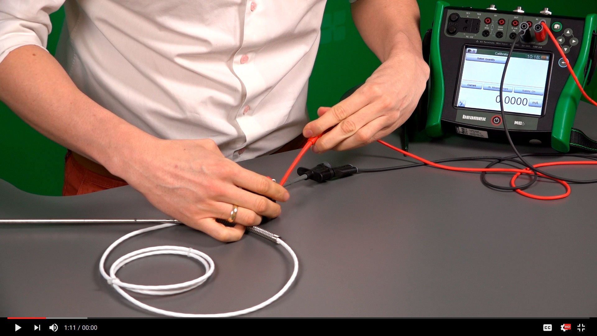
A practical test with a pressure transmitter
I tested the characteristics of the test connection/diode with one popular brand of a pressure transmitter.
The purpose of the test was to see how the current of the test diode changes when the voltage changes.
You can see the result of that test in the graphic below, and in the text and table after that.

A table of the data:

We can see in the results for example that:
- If you want to have smaller than a 0.01 % error, you better stay below about 275 mV - or have impedance less than 13.75 ohms.
- If you want to have smaller than a 0.05 % error, then you need to stay under 375 mV (or 18.75 ohms).
- At 400 mV the leak, current starts to grow quickly (equals 20 ohm mA meter impedance).
- At 500 mV the leak, current is 0.2 mA which equals over 1 % error when measuring 20 mA current (equals 25 ohm mA meter impedance).
As a result/summary of this test, I can say that:
- As long as your mA meter has impedance less than 15 ohms, you are good to go.
- If the impedance is 25 ohms, you will introduce over 1 % error in the measurement.
Accuracy effect of using the TEST connection
We can say that the accuracy using the test connection is good enough as long as you have mA meter with small enough impedance. If you don’t know the impedance of your meter, it may be risky to use the test connection.
Different transmitter models may have different characteristics than the one I tested.
How do you check the impedance of your mA meter?
How can you check the mA meter, or calibrator, you are using to see what impedance it has? Try checking the specification data sheet first, as it is often mentioned there. If the impedance is not specified, sometimes the voltage drop (or “Burden Voltage”) is specified as a certain voltage at a certain current. With this, you can calculate the impedance (U/I). For example, one device has a specification of 400mV at 20 mA, so you know the impedance is 20 ohms. Which means that it will add more than 0.1 % of error in 20 mA.
Sometimes, the impedance is anyhow not specified.
If it is not mentioned in the specs, then you can find it out in different ways:
- First, simply use a resistance meter and measure the impedance of the mA meter.
- Second, you can set a known current to go through the mA meter and then measure the voltage drop over it and calculate impedance/resistance (R= U/I). For example, if 20mA goes through the meter and the voltage drop is 0.2 V, then it has 10 ohm impedance (0.2 V / 20 mA = 10 ohm).
Transmitter manuals
With a quick search of pressure transmitter’s user manuals, I only found one popular pressure transmitter’s manual with a comment that the mA meter used in the test connection should have an impedance 10 ohms or less.
Yes, I do sometimes read manuals… if I really have to… ;-)
But for some reason I feel that generally the transmitter manufacturers do not mention this enough, or I have just missed that info (wouldn’t be the first time I miss something…).
Other ways to measure mA
Of course, there are also other ways to measure transmitter current, other than using the test connection.
For example:
- Break the current loop and add a mA meter in series with the transmitters. This is the most accurate way and any test diode leaks will not have any effect.
- I’ve seen people installing a precision resistor in series with the transmitter and then measuring the voltage drop over the resistor. You can then calculate the current without breaking the loop. Of course, the accuracy of the resistor will have an effect on the result.
- You can also use a clamp meter to measure the current in the loop. Most often the clamp meters are not very accurate though.
- You can also connect an external diode in series with the transmiter and use this the same way as the test connection is being used. You can add several diodes in series if you need it to work with a higher impedance mA meter.
So how about Beamex calibrators?
In Beamex calibrators, the impedance of the mA measurement has always been less than 10 ohms, typically around 7.5 ohms, so you can use them safely in the transmitter’s test connection.
However, please pay attention as there are also some calibrators, of well-known brands, in the market that have too a mA impedance which is too high for this application and will cause these issues.
Conclusion
I wrote this post as I have met this issue a few times with people. I would assume that there are more out there that would appreciate this information.
Well, at least it is now easier for me to answer this question when it gets asked next time. I will just ask them to read the answer in the blog … ;-)
Please let me know by comments if you found this information useful?
And finally, before you leave…
If you would like to get a short email when new posts are published in this blog, please subscribe by entering your email to the right-hand side “subscribe” field. Don’t worry, you won’t get emails more than roughly once in a month.
To check out the calibrators Beamex offers, please have a look at the below link:


.jpg)


Discussion