

In this post, I would like to talk you about the Ohm’s law. Why? Because it is helpful in many practical every-day situations, especially if you are an instrument technician. We often get questions that can be answered with an answer derived from the Ohm’s law.
Update November 1, 2018: Pictures has been replaced to include engineering units instead of quantities.
Although it is called “Ohm’s law” – don’t worry, this is not going to be any boring legal stuff… ;-)
First, I would like to talk a little about the theoretical side of it, and then take some practical instrumentation examples where you find this useful.
So, let’s take a look at this law...
Background
Let’s start with the compulsory facts:
Back in 1827, a German physicist Georg Ohm published this law. He discovered that when electric current goes through a resistor, the current is proportional to the voltage drop over the resistor and inversely proportional to the resistance of the resistor. The relationship between current, resistance and voltage is the Ohm’s law.
The Ohm’s law is often presented as a triangle (below triangle is shown with the engineering units):
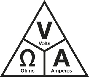
From the triangle, you can calculate each component and you get these three formulas:
- Resistance (Ohms) = Voltage (V) / Current (A)
- Current = Voltage / Resistance
- Voltage = Current * Resistance
Note: As the symbol for the quantity of voltage in the below examples, I will be using the symbol "U", according to the International SI System. I know that sometimes different symbols is being used for Voltage in different regions, such as E or V. The purpose of this post is not to try to standardize symbols, but to give practical education on the use of Ohm's law. So please don't get offended if you don't like the "U".
Please note that the mA current must be converted to Amps for the calculation.
Please also note, that for keeping the formulas simple and easy to read, I have not always used the mathematically correct number of significant figures/numbers. This post is anyhow more for technical people, not for mathematicians...
Simplified example
Let’s look at the most simplified possible circuit:

In the above example, we have a 24 VDC supply voltage and we have connected a 1200 ohms resistance into it. There is a 20 mA (0.02 A) current going through the circuit.
If we add a 1200 ohms resistor into the 24 V supply and we want to know what current goes in the circuit, we can calculate it easily with the Ohm’s law:
I = U / R = 24 V / 1200 ohms = 0.02 A (= 20 mA)
If we know the voltage is 24V and we want a current of 20 mA, we can calculate what resistor is needed:
R = U / I = 24 V / 0.02 A = 1200 ohms
Or, if we have a 1200 ohms resistor and we want to get 20 mA current, how much voltage do we need to apply:
U = I * R = 1200 ohm * 0.02 A = 24 V
Where:
U = Voltage [V]
I = Current [A]
R = Resistance [Ohm]
Consequently, if we have the 24 V loop supply and we want to get 4 mA current, we need to add a bigger resistance:
R = U / I = 24 / 0.004 A = 6000 ohms.
So, we need to add a 6000 ohms (6 kohms) resistor to get a 4 mA current.
Practical examples
Example 1 - A 250 ohms HART resistance
We have a normal circuit where the transmitter is supplied with a 24 V supply, and we have a 250 ohms resistor in series with the transmitter in order to use the HART communication:

As the current goes through the 250 ohms resistor, there is a voltage drop coming over that resistor, so some voltage is lost there. How much supply voltage comes to the transmitter when the current is 20 mA?
When the current is 20 mA we can calculate that over the 250 ohms resistor there will be a voltage drop of:
U = I * R = 0.02 A * 250 ohms = 5 V
This means there is a voltage drop of 5 volts over the 250 ohms resistor, so we have 19 volts left to the transmitter, which is of course enough for the transmitter to work. But if we had a much lower loop supply voltage, say 17 volts, to start with, there would be only 12 volts left to the transmitter, which is on the limit for it to work.
Ex 2 - Measuring transmitter’s current with a resistor in series
If you don’t want to break the loop or open the transmitter’s cover to measure the current, you can install a precision resistor in series with the transmitter and then measure the voltage drop over the resistor to calculate the current.

The voltage drop over the resistor depends on the resistance value and on the current going through it. For example, if you install a 100 ohms resistor in series with the transmitter, the voltage drop over it will be:
At 4 mA => 0.004 A * 100 ohms = 0.4 V
At 20 mA => 0.02 A * 100 ohms = 2.0 V
Of course, the resistance needs to be very accurate and stable, because any error in the resistance value will give a similar error in the calculated current.
The bigger the resistance is, the bigger voltage you get. It is good to remember that if the resistance is very big, then you will lose a lot of supply voltage over the resistor.
Ex 3 - mA meter’s resistance with transmitter’s test diode connection
This is a topic I discussed in an earlier blog. In that example, understanding of the Ohm’s law was also needed to understand the issue. You can find that blog post in the below link:
Measuring current using a transmitter’s test connection – don’t make this mistake!
Ex 4 - Supply for high resistance circuit
You may have a circuit where the instrument has a high internal resistance. Let’s say an old I/P converter that has 800 ohms resistance. You need to generate a 4 to 20 mA signal to control the converter. How much supply voltage would you need to do that?
Well, in order to generate a current of 20 mA over that 800 ohms circuit, you will need:
U = I * R = 0.02 A * 800 ohms = 16 Volts.
So, you will need a loop supply that has a voltage of at least 16 volts.
Ex 5 - Too much resistance in the supply line
If there is too much resistance in the supply line to transmitter, the loop supply to the transmitter can be on the edge of being too small, it may happen that the transmitter works perfectly with lower mA signal, but when it needs to deliver high current (for example over 18 mA), the voltage drops too low and the transmitter will switch itself off. This is simply because the voltage drop in the connection resistances becomes bigger as the current become bigger. It can happen that with a small current the voltage is acceptable and the transmitter gets enough supply voltage, but with higher current there is too much voltage drop in the connections and the transmitter does not get high enough voltage, and switches off.
When the transmitter goes off, the current drops and the supply voltage jumps back up again and the transmitter starts to work again normally. This kind of intermittent faults are very difficult to find.
Ex 6 - mA meter / Volt meter
It is also good to remember that in practice, a mA meter’s internal resistance is not zero ohms, but it has a certain internal resistance (a few ohms or tens of ohms). So, there will be some voltage drop over the mA meter in practice.
Also, a voltage meter does not have infinite resistance, but it has a certain internal resistance (megaohms). These resistances may cause some unwanted effects when you make your measurements. So, the voltage meter will put some load on to the measured circuit, although this is an issue only valid in certain sensitive circuits/ applications. This is especially important when you are measuring a low voltage (tens or hundreds of millivolts) signal in a high resistance circuit and you have a high accuracy requirements (± a few microvolts). If the voltage meter has too small resistance, the measured voltage will drop as soon as you connect the voltage meter, so you don’t get accurate results. In some case connecting voltage meter with too low internal resistance may cause the circuit to trip as soon as you connect the meter.
Conclusion
The Ohm’s law is pretty simple and easy to understand. It has many applications if you work with electrical circuits. It is often very useful also in the instrumentation world, where you work with loop supply, current signals and resistances.
I hope this post was easy and practical enough to give you some useful tips for your work.
Download the related white paper by clicking the below picture:

Thanks!


.jpg)


Discussion