
Comparing the accuracy specifications of pressure calibrators can be a challenging task because different manufacturers specify accuracy in different ways. This means that you can’t simply compare the numbers given in the specification – you need to understand how these numbers are calculated and what they mean in practice.
In this blog post, I look at the different ways pressure calibrator accuracy specifications are presented, explain what they mean, and compare them, as well as take a brief look at what else you should consider when choosing a pressure calibrator.
Table of contents
Other things to consider
TAR & TUR vs. calibration uncertainty
Finally, it's not only about accuracy
Beamex solutions for pressure calibrations
Related blog posts

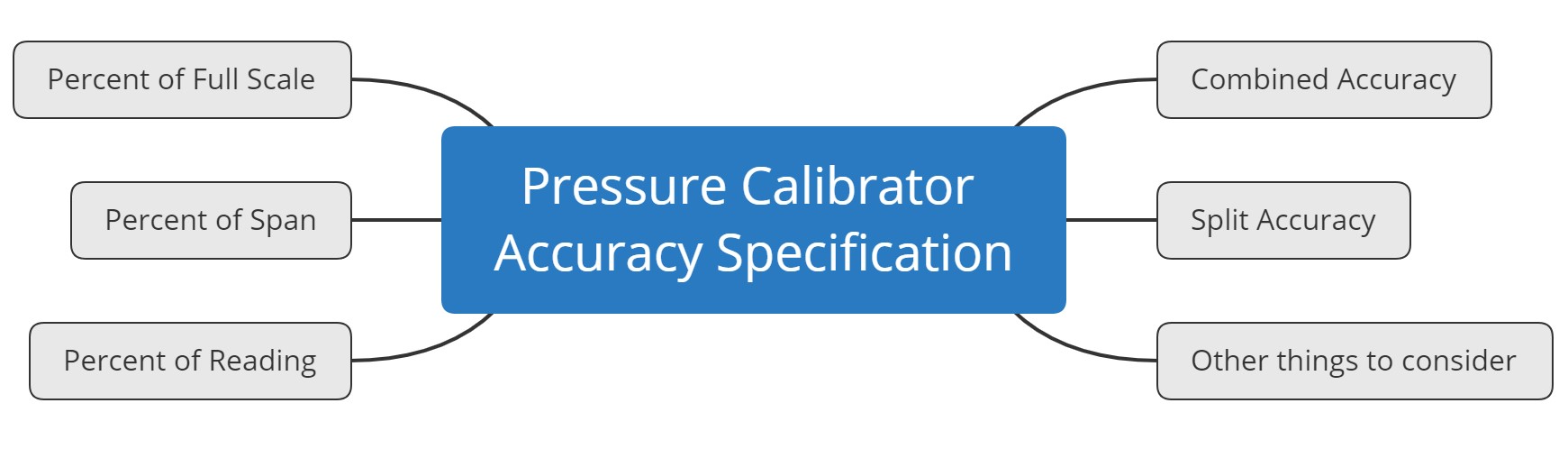
Accuracy specifications
First, let’s look at the different ways accuracy specifications are provided by manufacturers and how to interpret them.
1. Percent of full scale
Percent of full scale (sometimes written also "% of full scale", or "% FS") is one of the most common ways to specify pressure measurement accuracy, and many process instruments use this kind of accuracy specification.
As the name suggests, you calculate the given percentage value from the full scale of the pressure range, with full scale being the maximum pressure the module can measure.
With percent of full scale, measurements have the same (absolute) accuracy (or error) throughout the whole range. This specification is obviously an easy one to calculate and understand.
It is best suited to technologies where the zero and full scale have a similar likelihood for error or drift, and where it is not possible for the user to easily make a zero correction during normal usage.
With most modern electrical pressure measurement devices, the user can perform zeroing of the pressure measurement by having the pressure measurement open to atmospheric (ambient) pressure and performing a zeroing function. This makes it easy for the user to correct for any zero errors before and after a measurement is taken. Therefore, % FS is not the most suitable accuracy specification for modern electric pressure measurement equipment.
Example
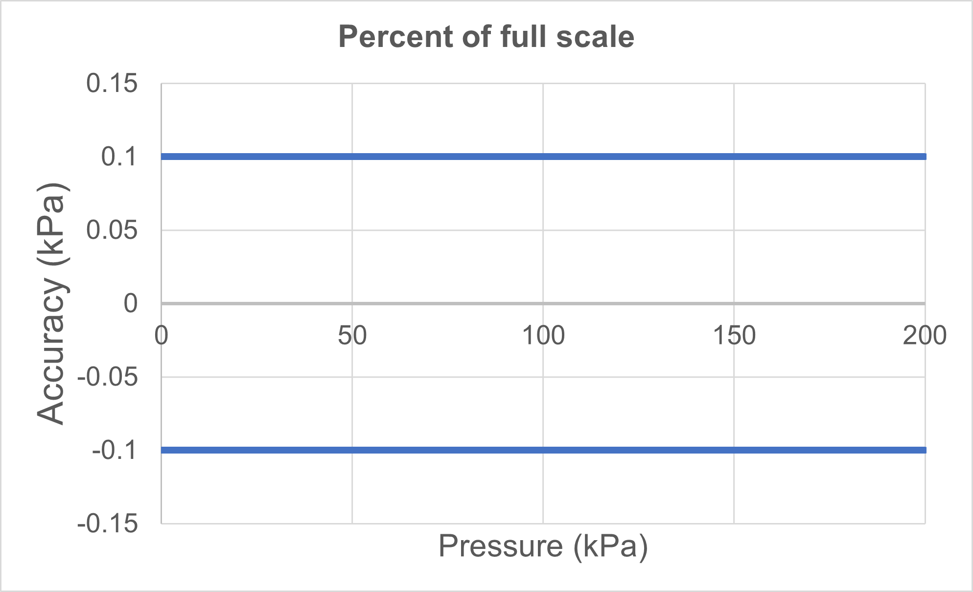
For clarification, let’s look at some examples with graphs for all the different specification methods, starting with the "percent of full scale" method.
- Pressure range: 0 to 200 kPa
- Accuracy specification: ±0.05 percent of full scale (%FS)
As we can see in the first image below, the accuracy specification is a flat line and remains the same in engineering units (0.1 kPa) throughout the pressure range whether we use %FS or kPa on our Y-axis.
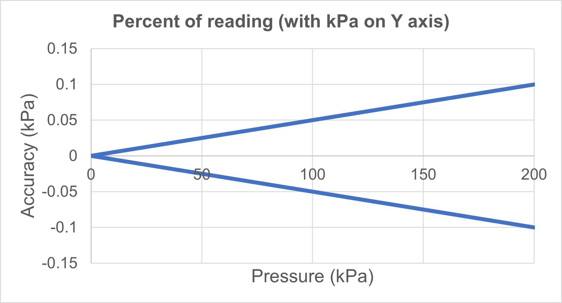
But if we look at the accuracy specification as the accuracy of the measured pressure point (or accuracy as a "percent of reading" value), then the situation is different as the second graph below shows.
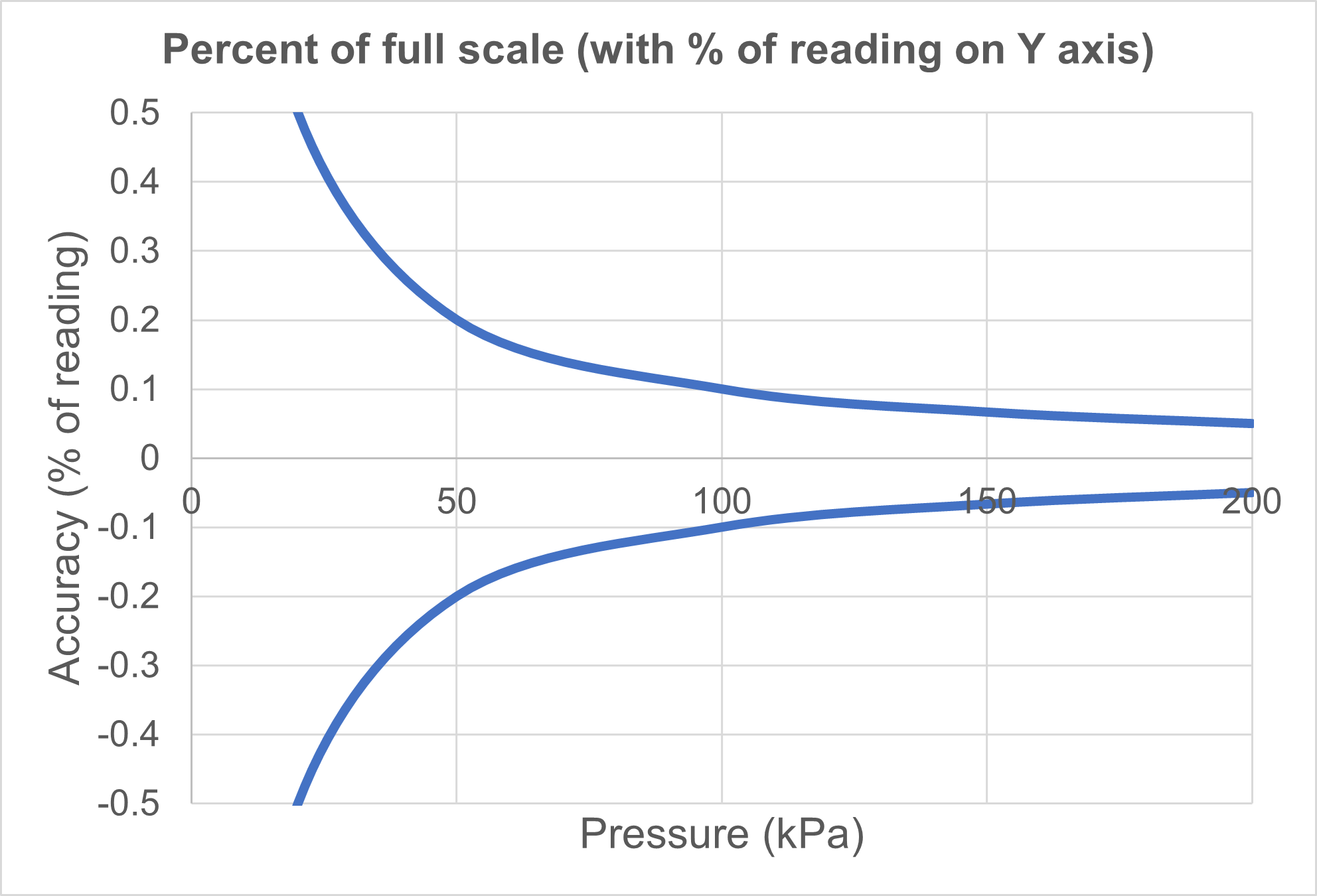
The above graph shows the percentage of the accuracy reading on the y axis. This shows what is happening in practice when you measure a certain pressure with this kind of module, showing how accurate that measurement is compared to the pressure being measured.
We can see that the error of the actual measured pressure will increase pretty quickly if we are measuring a pressure smaller than the full scale.
A %FS specified pressure measurement should be mainly used with pressures close to the upper end of the module, as it loses accuracy pretty quickly at lower pressures. If you measure very low pressures the error of that measured pressure can be huge.
For example, when measuring a pressure in the middle of the range (at 50% point), the error on that reading is already doubled on the error at full scale point. Measuring at 25% of the range point, the error is quadrupled!
If you have pressure modules with %FS accuracy specification, you end up needing several modules as the accuracy deteriorates quickly when measuring lower pressure.
Accuracy expressed in ppm or engineering units
These two methods are very close to the percent of full scale method.
Sometimes the accuracy can be expressed in ppm (parts per million) of the full scale. Obviously, as the percentage is 1/100 and ppm is 1/1 000 000, there is a multiplier of 10 000 between the two.
For example, 0.05 %FS equals 500 ppm FS, so it is very similar to the %FS way of expressing accuracy. Of course, ppm can also be used for reading error, but more on that later.
Sometimes accuracy is also expressed in engineering units. For example, in the above example, the accuracy could have also been expressed as ±0.1 kPa, instead of ±0.05 %FS.
2. Percent of span
Percent of span is similar to the percent of full-scale method, but instead of calculating the percentage from the maximum range value (full scale), it is calculated from the whole range.
Naturally, if the range starts from zero, there is no difference between %FS and percentage of span accuracy.
A pressure measurement range is anyhow often a “compound” range, i.e. it starts from the vacuum side and continues to the positive side. So, for example, the measurement range could be from -100 kPa to +200 kPa. In this case, the percentage is calculated from the whole span (300 kPa, the difference between the minimum and maximum values) instead of the full scale (200 kPa).
For a fully symmetric pressure range (e.g. -1 bar to +1 bar, or -15 to +15 psi), an accuracy specification of “±0.05 % of span” has twice the error of a “±0.05 % of full-scale” specification.
Example
- Pressure range: -100 kPa to +200 kPa
- Accuracy specification: ±0.05 % of span
The above example looks graphically as the image below:
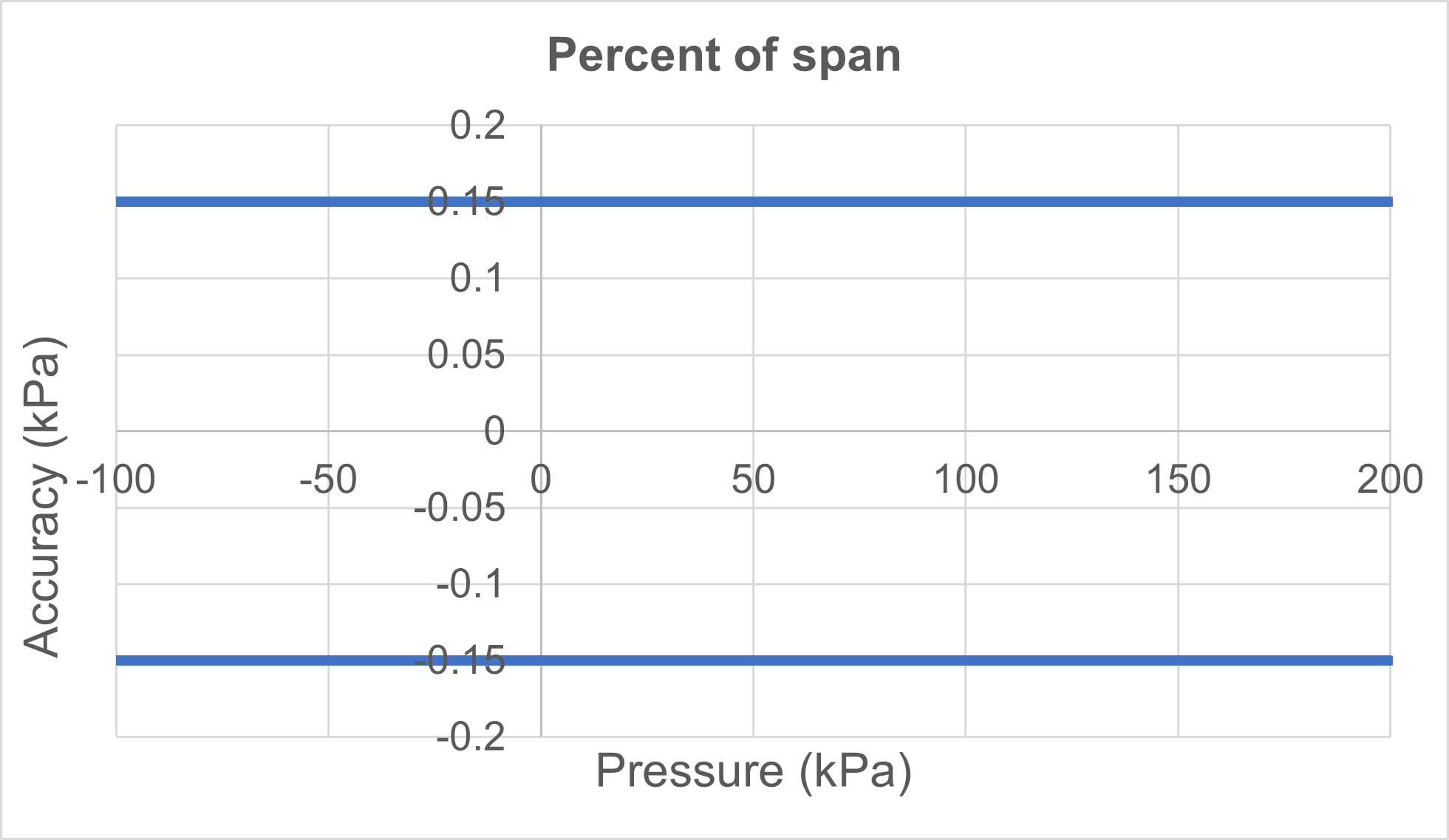
In practice, a compound range is most often not fully symmetrical, with the positive side of the range typically larger than the vacuum side. Of course, the vacuum side can never exceed a full vacuum, but the positive side can be any size.
With a compound range, the positive side does not typically measure to very high pressure, because if a high-pressure sensor is used it will not be accurate on the vacuum range.
3. Percent of reading
With percent of reading accuracy specification (sometimes written "% of reading", "% of rdg", or "% rdg"), accuracy is always calculated from the measured pressure value.
With this kind of specification, the absolute size of the error (accuracy) changes as the measured pressure changes.
Obviously, this also means that at zero the accuracy specification is zero, and at very close to zero it is very small or negligible. So in practice, it is very unlikely that you will see a percent of reading specification used on its own.
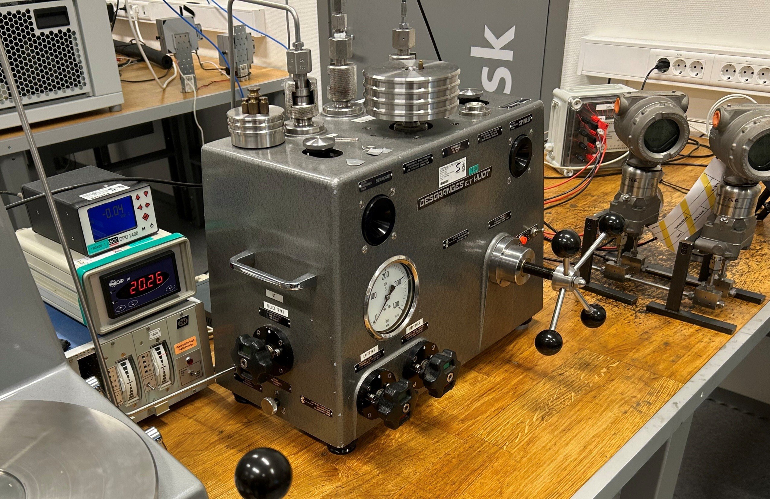
Traditional dead weight testers commonly have accuracy specified as a percent of reading. In practice, the lowest pressure that can be generated with a dead weight tester is limited by the smallest available weight, or the lowest pressure at which the accuracy specification is valid is specified.
A pure percent of reading accuracy specification is not well suited to electronic pressure measurement devices or calibrators because the accuracy gets very small close to zero, and the accuracy is zero at zero pressure.
That is not practical, as there is always some noise or zero drift, so it is not realistic to provide only a percent of reading accuracy specification for electronic calibrators. If this is the only specification provided, then the range minimum, i.e. the limit below which the accuracy specification is no longer valid, should also be specified.
Percent of reading may also be given as a ppm specification. This is more practical with high-precision instruments (e.g. dead weight testers) as a percentage figure would soon start to have many zeros. As explained earlier, converting a percentage figure to ppm means multiplying the percentage by 10 000.
Example
- Range: 0 to 200 kPa
- Accuracy specifications: ±0.05 percent of reading
The graphic below has the Y-axis as "% of reading", which is obviously a straight line.
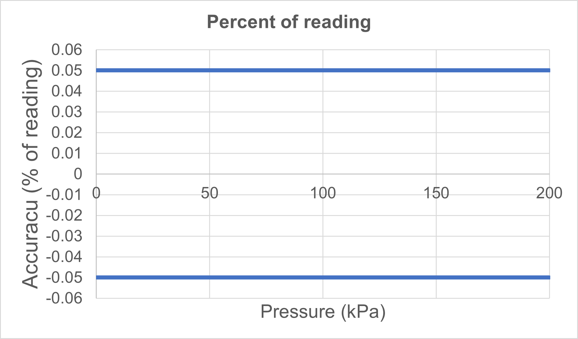
The below graphic shows a "% of reading" accuracy, with the absolute accuracy (engineering units, kPa in this case) on the Y-axis. We can see that when the pressure value is small, the absolute error is small. As the pressure increases, the absolute error increases.
4. A combined accuracy (percent of full scale and percent of reading)
This means that the accuracy specification is a combination of percent of full scale and percent of reading.
The percent values of each may be different. For example, the accuracy specification can be expressed as ±(0.01% of full scale + 0.05% of reading).
In practice this means that the "% of full scale" part ensures that there is a valid accuracy specification at zero and close to zero, while the "% of reading" part means that the absolute accuracy specification grows as the pressure grows.
This kind of specification is pretty common for electrical pressure measurement devices.
The below example and graphic illustrates this type of specification.
Example
- Pressure range: 0 to 200 kPa
- Accuracy specification: ± (0.01 % of full scale + 0.04 % of reading)
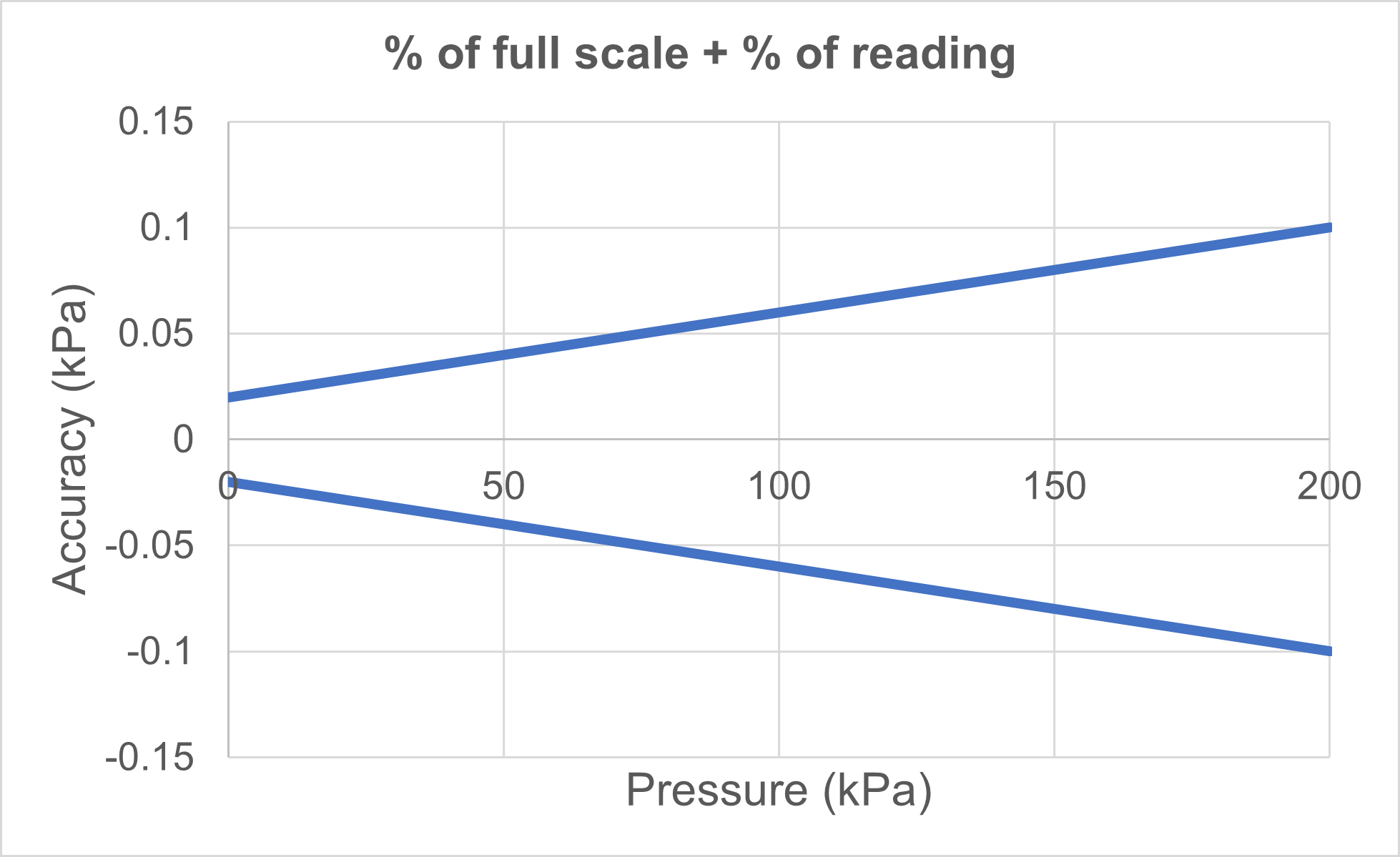
In the above example, the combined accuracy at the full scale value is ±0.1 kPa, which is the same as for the ±0.05% of full scale specification, so the accuracy at the full scale point is the same.
However, because part of this specification is given as percent of reading, the module is pretty much more accurate at lower pressure than a 0.05% of full scale module.
So, this kind of pressure calibrator is better at performing calibrations at lower pressures without sacrificing accuracy than a calibrator with only a percent of full scale accuracy specification. Also, with this kind of combined specification you end up needing less different range pressure modules, as they are more accurate on a wider pressure range.
5. A split range accuracy
This means that the lower part of the pressure range has a fixed accuracy (% of full scale, % of span, or engineering unit) and the upper part has a percent of reading specification.
This is another way for manufacturers of electrical calibrators to ensure that they can provide credible accuracy specifications at and close to zero, and also that the absolute accuracy specification increases as the pressure increases.
The lower part of the range may be specified as a percent of full scale, part of the scale, or as a percent of a (fixed) reading. It may also be given in engineering units.
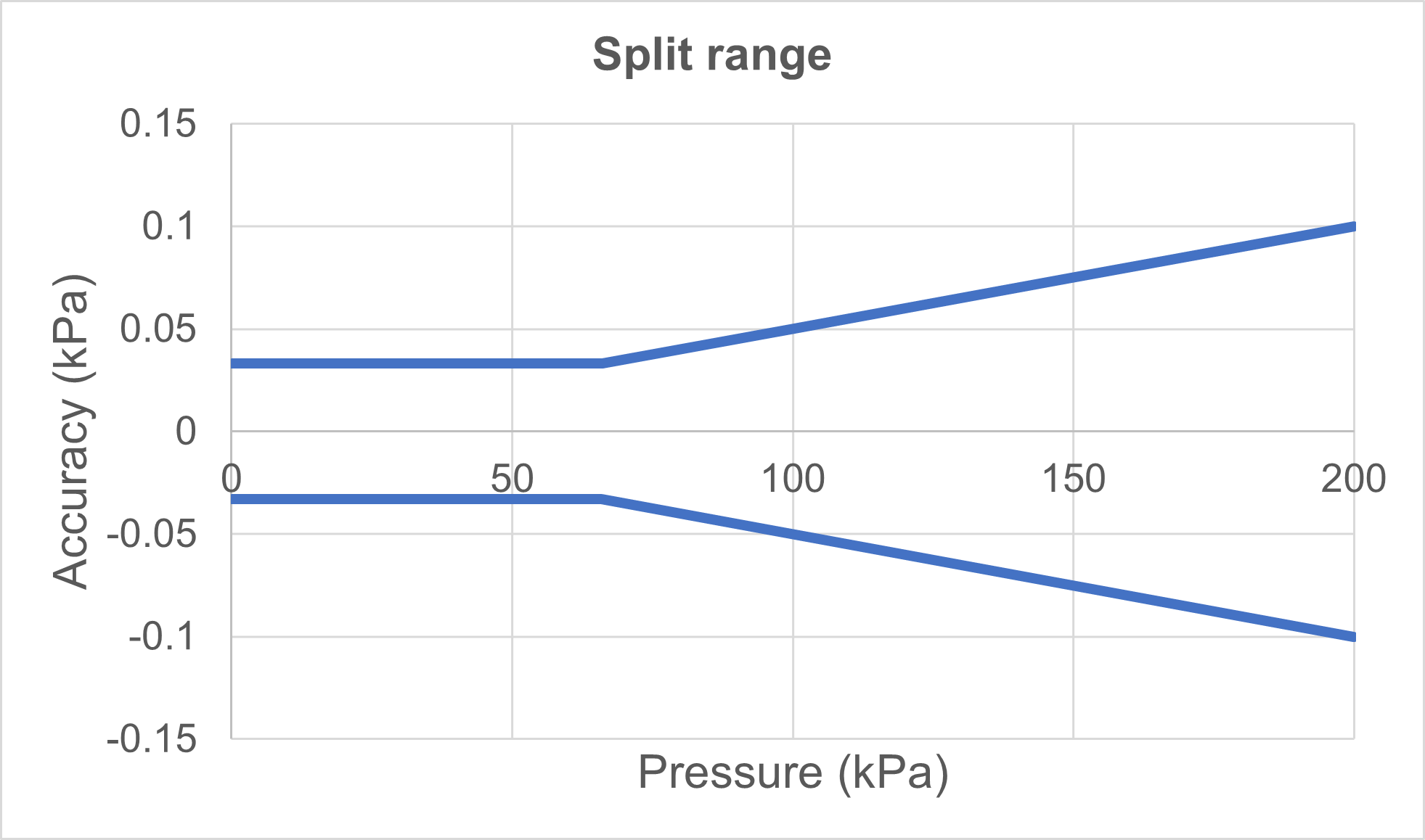
In practice this means that the lower part is “flat” and the upper part is growing. The example and graph below illustrate this concept.
Example:
- Pressure range: 0 to 200 kPa
- Accuracy specification: "0.01% of full scale" for the first third of the range plus "0.05% of reading" for the rest of the range
Other things to consider
Long-term stability
Often, the given accuracy specification is not valid for longer periods of time and does not include any long-term drift specification. Be sure to read the small print in the calibrator’s documentation to find out if this is the case.
If you calibrate the pressure calibrator once a year, for example, it is important to know what kind of accuracy you can expect from the calibrator just before the next calibration, i.e. 11.5 months after the previous one.
For electrical pressure calibrators, where the user can make a zero correction, the zero does not drift over time (or it can be zeroed away by the user).
But the user can’t correct the drift at higher pressures (span drift). The drift normally changes the accuracy at higher pressures, typically adding a “percent of reading” type drift over time, so the full-scale span typically drifts more over time.
When choosing a pressure calibrator, be sure to check its long-term drift specification.
Uncertainty vs. accuracy
Another vital consideration is what components the accuracy specification includes.
Some calibrators offer an uncertainty specification instead of an accuracy specification. Typically, this means that the uncertainty specification also includes the uncertainty of the reference standards used in the calibration laboratory when manufacturing and calibrating the calibrator. Also, it often specifies the validity period for the specification, for example one year.
Generally speaking, uncertainty is a more comprehensive concept than accuracy. I could write a lot about uncertainty, but for now it’s enough to mention that you should make sure that you know all the uncertainty components relevant to the whole calibration event because the total uncertainty of the calibration process is often much more than just the calibrator’s specification.
If interested, you can read more about uncertainty in the Calibration uncertainty for dummies blog.
TAR & TUR vs. calibration uncertainty
Commonly used criteria for calibrator (reference standard) accuracy is the test accuracy/uncertainty ratio (TAR and TUR). This is the ratio of accuracy or uncertainty between the calibrator and the instruments to be calibrated with it and it is used to determine the level of accuracy you require from your calibrator. The bigger the ratio, the better it is. Common traditional industry practice is to use a 4 to 1 ratio.
Often the process instruments to be calibrated will have a percentage of full scale accuracy specification, while the calibrator may have (partly) a percentage of reading specification.
In practice, this means that the calibrator’s accuracy is greater than that of the process instrument when the measured pressure is smaller than the full scale.
So even if the test accuracy ratio (TAR) is not big enough at full scale pressure, it gets bigger (better) as you measure a lower pressure. The example below explains this.
I think the below graphic needs some explanations:
- The blue line is the process instrument's accuracy (to be calibrated), it is 0.2 % of full scale (=0.4 kPa) [Left Y axis]
- The green line is the calibrator accuracy, being 0.05 % of reading [Left Y axis].
- The red line is the TAR (test accuracy ratio), i.e. the ratio been the two above accuracies (read on the right Y-axis). We can see that the TAR is 4 at the full scale value, but as soon as the pressure comes smaller the ratio increases a lot because the calibrator has a "% of reading" specification while the process instrument is a "% of full scale" [Right Y axis]
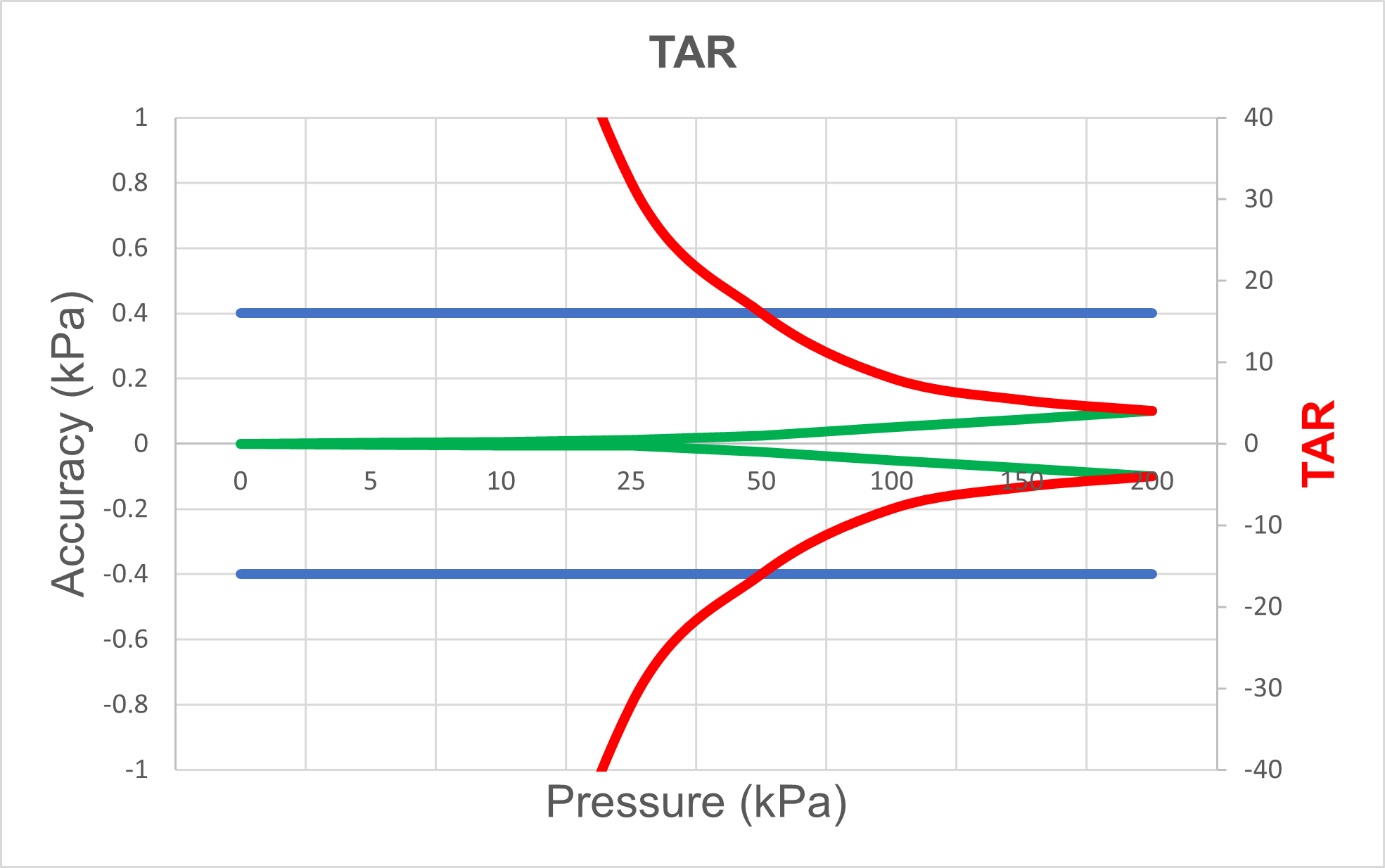
The main takeaway with this (maybe confusing) above graphic is that the TAR should be calculated at different pressure values. Even if it looks like not being enough at full scale, it may be well enough at lower pressure, assuming the calibrator accuracy has at least partially a "% of reading" component.
Please note that a TAR only includes an accuracy comparison, which means it is missing all the uncertainty considerations. In practice, calibration processes can include other larger uncertainty sources than the calibrator, so it is important to determine the total uncertainty of the calibration process.
Environmental specification
It is important to read the specifications carefully to understand which environmental conditions the given specifications are valid for. If you are performing calibrations in the field rather than in a controlled environment like a laboratory or workshop, then the conditions will vary a great deal.
Sometimes the given specifications are valid only at a specific temperature or within a limited temperature range. There can be a separate specification outside that range, or a temperature coefficient.
Other environmental conditions to consider include humidity, altitude, ingress protection, orientation effect, warm-up time, and shock/vibration.
In summary, be sure to check the environmental specifications that are relevant for you when comparing pressure calibrators.
Additional components
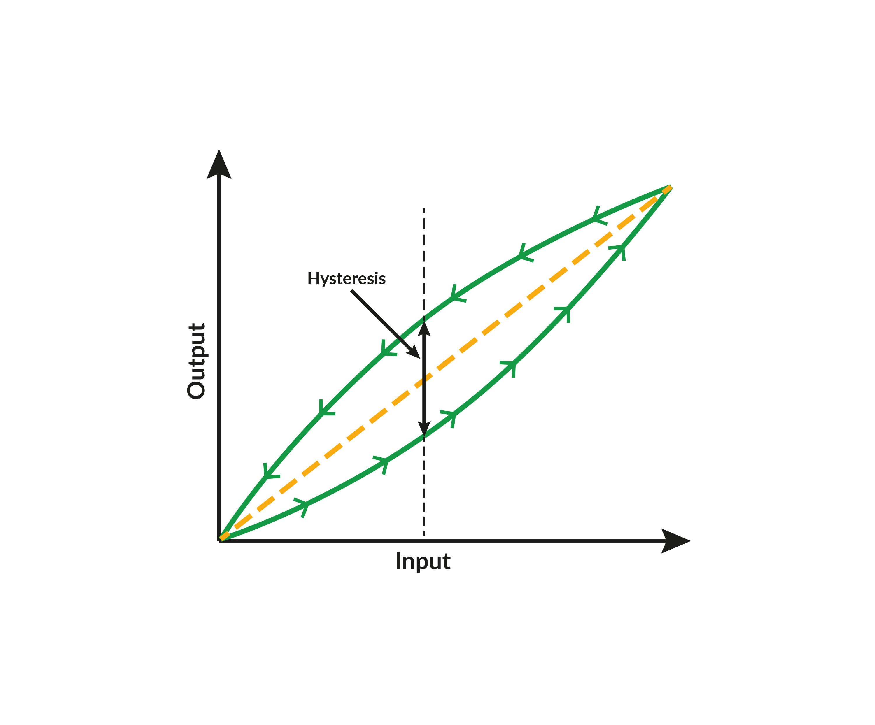
Does the specification include all relevant components – like hysteresis, nonlinearity, and repeatability – or are these specified separately and need to be added to the specification.
Finally, it’s not only about accuracy
Although accuracy and uncertainty are vital considerations when choosing a pressure calibrator, there are also other things to consider when selecting one, such as:
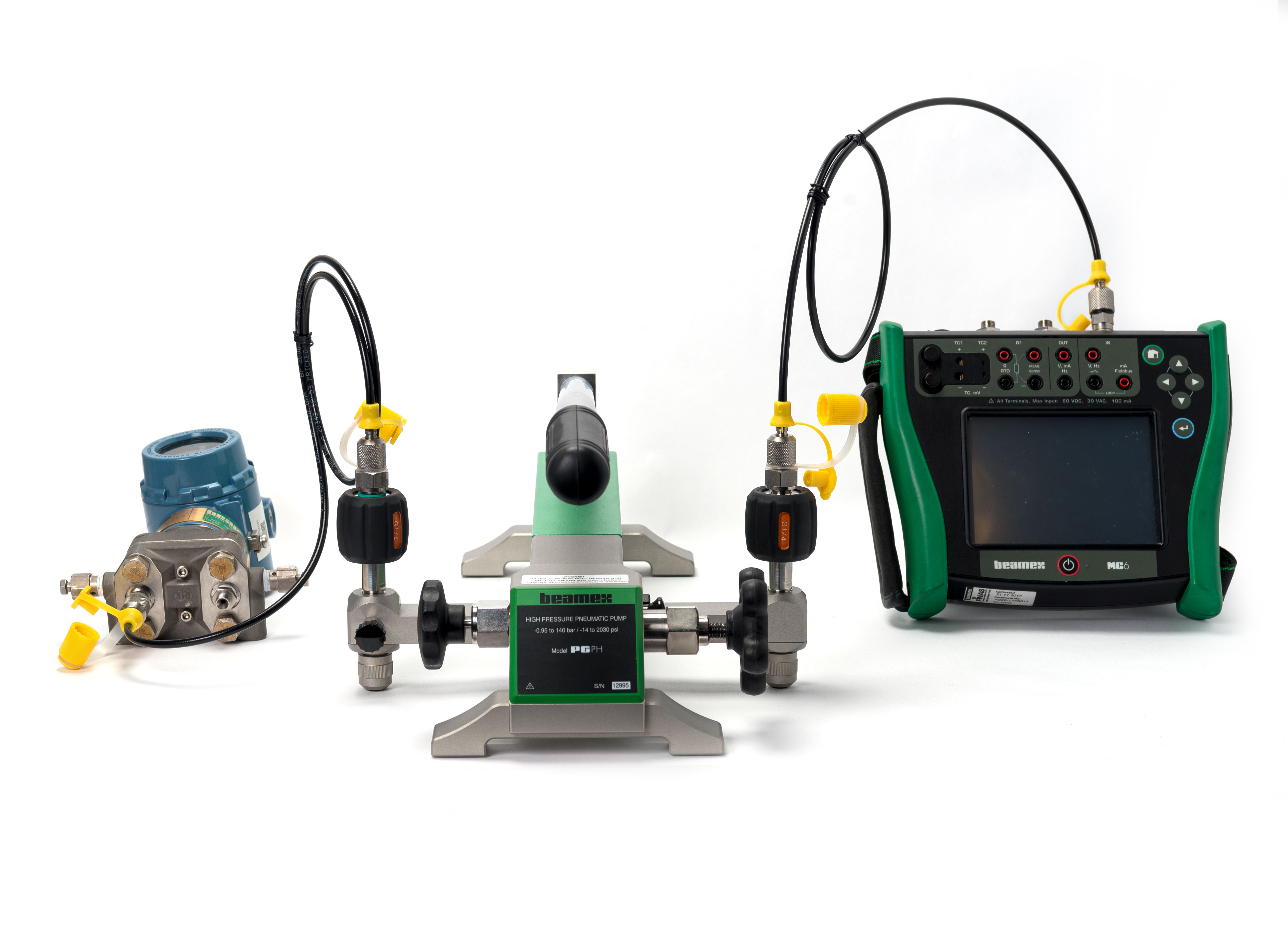
- Does the calibrator include overpressure protection? It is difficult to avoid over-pressurizing a pressure measurement device every now and then. Some pressure calibrators have sensors that can be damaged by even the slightest amount of overpressure, while others can withstand a certain level of overpressure without damaging the sensors or affecting the accuracy. For example, the Beamex MC6 Advanced Field Calibrator and Communicator includes a built-in relief valve to release overpressure and prevent damage.
- Does the calibrator come with an accredited calibration certificate ensuring the formal metrological traceability? If not you may need to have it calibrated separately.
- How conservative or aggressive are the specifications? Although difficult to see, it would be good to try to find out if the company normally gives reliable conservative specifications, or if it gives aggressive figures.
- The brand of the company. Who manufactures the device? Is the manufacturer reliable?
- What are the warranty terms and conditions, and is there the option to extend the warranty and purchase a service plan to cover items that don’t fall within its scope?
- Are there training services available? How is the support arranged and available? How is recalibration arranged?
- What functions other than pressure measurement does the calibrator provide that are useful for you?
- For example, a 24 V loop supply and accurate mA measurement are handy if you plan to calibrate pressure transmitters.
- Most transmitters are HART enabled, so if the calibrator includes a HART communicator, you don’t need to carry a separate communicator with you.
- Calibrations need to be documented, so how do you plan to do that? A documenting pressure calibrator will automatically document calibration results and can communicate with your calibration software, saving you time and effort and eliminating the risk of manual data entry errors.
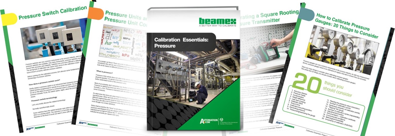
Download a pdf version of this article by clicking the image below:

Beamex solutions for pressure calibration
Beamex offers various different high-accuracy solutions for pressure calibration, such as:
- Portable pressure calibrators; MC6, MC2, MC4.
- Intrinsically safe pressure calibrators; MC6-Ex.
- Pressure calibrators for workshop solutions; MC6-WS.
- Automatic pressure controllers; POC8.
- Portable electrical pressure pump; ePG.
- Calibration hand pumps; PG series.
- Calibration management software solutions; CMX, LOGiCAL.
Check out all Beamex pressure calibrators.
Related blog posts
Beamex blog includes several posts related to pressure calibration, but if pressure is your thing, please check at least these:
- Pressure Calibration [eBook]
- Pressure Switch Calibration
- Pressure Transmitter Accuracy Specifications – the small print
- How to calibrate pressure instruments [Webinar]
- How to calibrate pressure gauges - 20 things you should consider
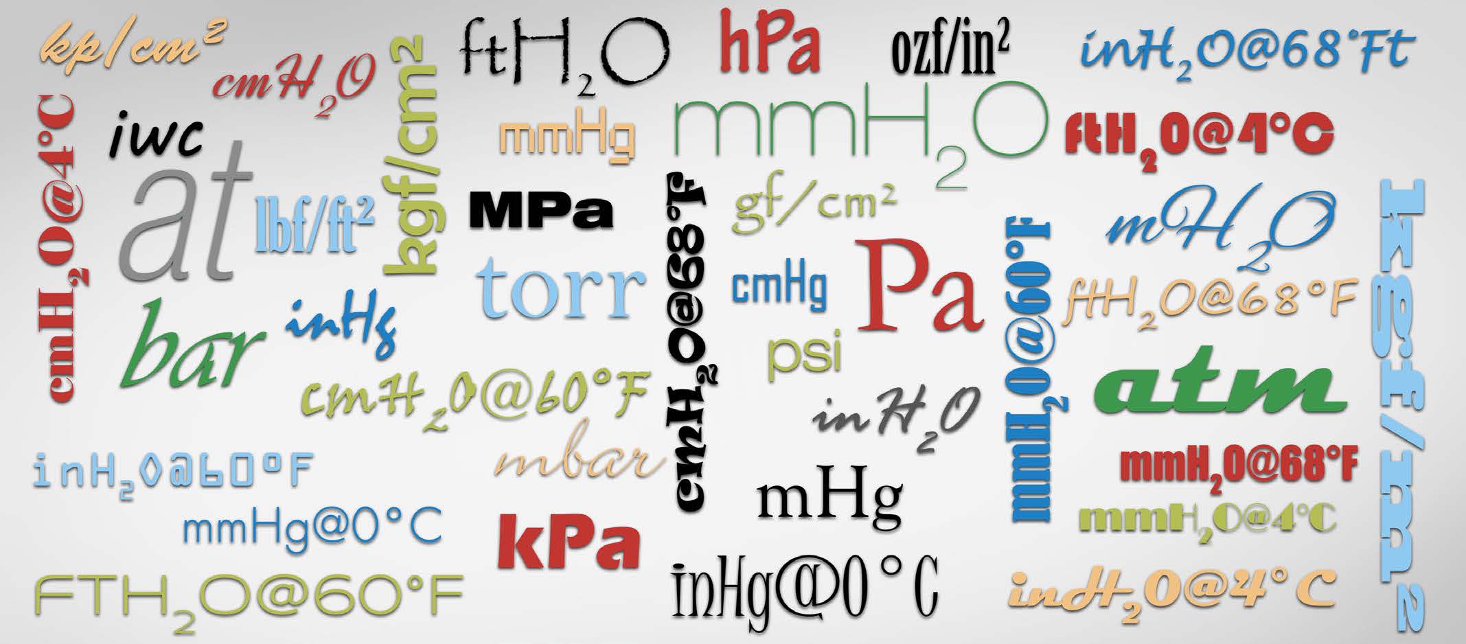
- Pressure units and pressure unit conversion
- Pressure calibration basics – Pressure types

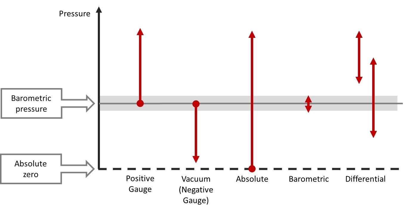


.jpg)


Discussion