
Pressure Gauge Calibration
20 things you should consider when calibrating pressure gauges
Pressure gauges are very common instruments in the process industry. As with any measurement device, pressure gauges need to be calibrated at regular intervals to assure they are accurate. There are many things to consider when calibrating pressure gauges. This article lists 20 things you should consider when calibrating pressure gauges.
Please download related free white paper by clicking the below picture:

Content - The 20 things you should consider
The 20 things discussed in the article are the following:
1. Accuracy classes
2. Pressure media
3. Contamination
4. Height difference
5. Leak test of piping
6. Adiabatic effect
7. Torque
8. Calibration / mounting position
9. Generating pressure
10. Pressurizing / exercising the gauge
11. Reading the pressure value (resolution)
Remaining topics in the free white paper:
12. Number of calibration points
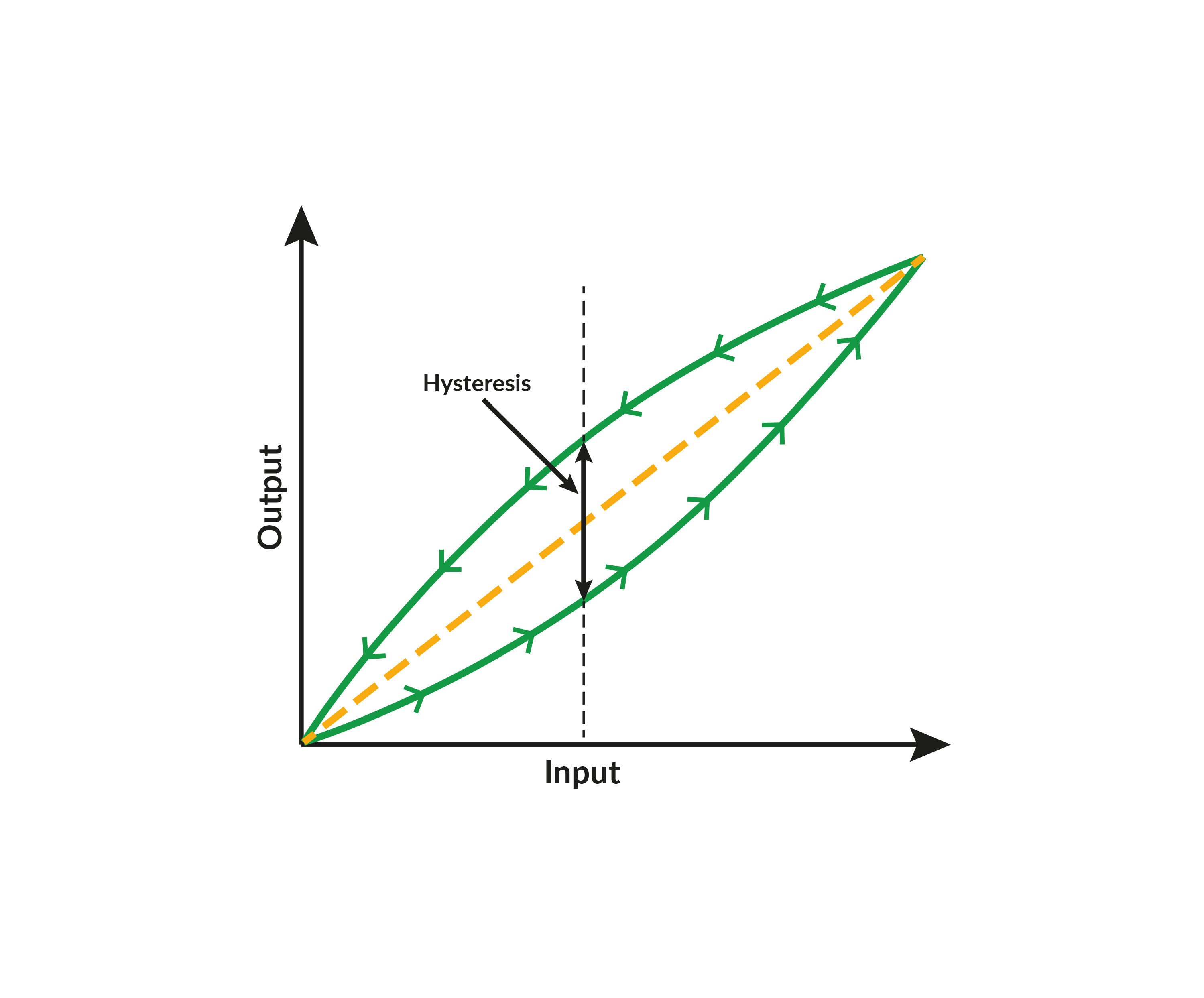
13. Hysteresis (direction of calibration points)
14. “Tapping” the gauge
15. Number of calibration cycles (repeatability)
16. Adjustment / correction
17. Documentation – calibration certificate
18. Environmental conditions
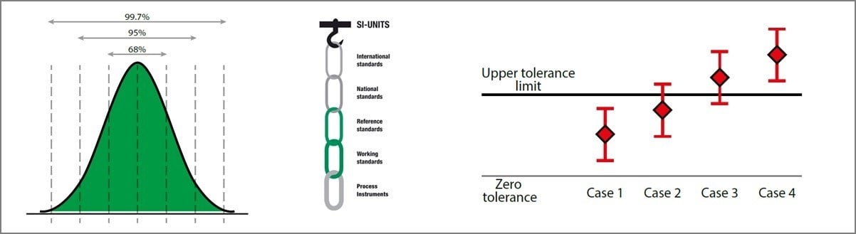
19. Metrological traceability
20. Uncertainty of calibration (TUR/TAR)
What is pressure?
Before we discuss each one of the things to consider when calibrating pressure gauges, let’s take a quick look into a few more basic concepts.
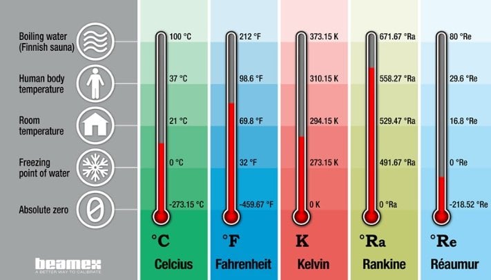
What is pressure? Pressure is the force that is perpendicular to the surface divided by the area it is effecting. So pressure equals force per area, or p = F / A.
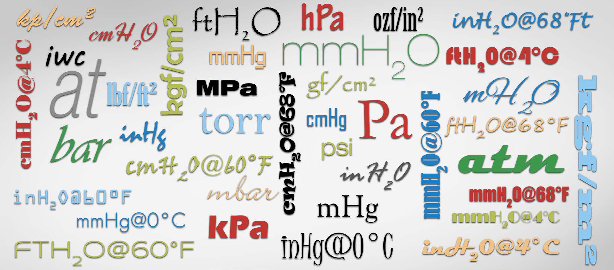
There are a large number of different pressure units used around the world and this can be sometimes very confusing. The engineering unit for pressure, according to SI system, is Pascal (Pa), being a force of one Newton per one square meter area, 1 Pa = 1 N / m2. Since Pascal is a very small unit, it is most often used with coefficients, such as hecto, kilo and mega. A large number of different pressure units are being used around the world. For more information on pressure and different pressure units and their background, please see the blog post Pressure units and pressure unit conversion.
For an on-line pressure unit conversion tool, please visit the page Pressure unit converter.
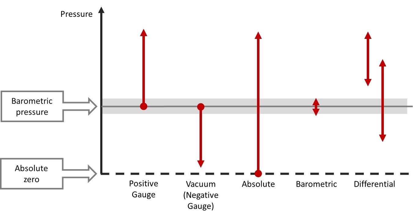
Pressure types
Several different pressure types exist including gauge, absolute, vacuum, differential and barometric. The main difference of these pressure types is the reference point against which the measured pressure is being compared. Pressure gauges also are available for all of these pressure types. Also, compound gauges are available, including a combined scale for both positive gauge pressure and vacuum (negative gauge) pressure.
For more detailed information on different pressure types, please see post Pressure calibration basics – pressure types.
Pressure gauges
When talking about pressure gauges, it is normal to refer to analog pressure indicators which are provided with a pointer needle and a pressure scale. These are normally manufactured according to EN 837 or ASME B40.100 standard.
Often these kind of analog pressure gauges are built with a Bourdon tube, diaphragm or capsule. There is a mechanical structure that moves the pointer as pressure increases causing the pointer move across the scale.
Pressure gauges are divided into different accuracy classes that specify the accuracy of the gauge as well as other attributes. Available pressure ranges are typically divided in steps with coefficients 1, 1.6, 2.5, 4, 6 continuing into the next decade (10, 16, 25, 40, 60) and so on. The different gauge diameters (of scales) are typically 40, 50, 63, 80, 100, 115, 160 and 250 mm (1 ½, 2, 2 ½, 4, 4 ½, and 6 inches). More accurate gauges typically have a bigger diameter.
Pressure connectors are normally parallel pipe threads (G) according to ISO 228-1, or taper pipe threads (NPT) according to ANSI/ASME B1.20.1.
There are also digital pressure gauges that have a numeric pressure indication instead of an analog pointer. This article focuses on analog gauges, but most of the principles are valid for both.
Pressure gauges are commonly used in all industries and are a very common instrument to be calibrated. As with any process measurement device, it should be calibrated at regular intervals to assure that it is measuring correctly. Gauges being mechanical instruments, adds the risk for them to drift due to mechanical stress.
For more information on why you should calibrate instruments, please see the blog post Why calibrate?
For more information on how often instruments should be calibrated, please see post How often should instruments be calibrated?
The basic principle of calibration
If we simplify the principle of a pressure gauge calibration to its minimum, we can say that when we calibrate a pressure gauge, we provide a known accurate pressure input and read the indication on the gauge, and then document and compare these. The difference in the values is the error and the error should be smaller than the required accuracy for the gauge.
20 things you should consider
This section lists the 20 most common things you should consider when you are calibrating pressure gauges.
1 - Accuracy classes
Pressure gauges are available in many different accuracy classes. Accuracy classes are specified in ASME B40.100 (accuracy classes from 0.1 to 5 % range) as well as in EN 837 (accuracy classes from 0.1 to 4 % range) standards. The accuracy class specification most often being “% of range” means that if the accuracy class is 1% and if the scale range is zero to 100 psi, the accuracy is ± 1 psi.
Make sure you know the accuracy class of the gauge you are going to calibrate, as this will naturally specify the acceptable accuracy level, but it will also have other effects on the calibration procedure.
Back to top ⇑
2 - Pressure media
When calibrating pressure gauges, the most common pressure media are gas or liquid. Gas is most often regular air, but in some applications, it can also be different gases, such as nitrogen. Most commonly, the liquid is water or oil. The pressure media during the calibration depends on the media that is used in the process that the gauge is connected to. Media also depends on the pressure range. Low pressure gauges are practical to calibrate with air/gas, but as the pressure range gets higher it is more practical and also safer to use liquid as the media.
Back to top ⇑
3 - Contamination
While installed in a process, the pressure gauge uses a certain type of pressure media, this should be taken into account when selecting the media for the calibration. You should not use a media during the calibration that could cause problems when gauge is installed back to process. Also, the other way around, sometimes the process media could be harmful to your calibration equipment.
There can be dirt inside the gauge that can get into the calibration equipment and cause harm. With a gas operated gauges, you can use a dirt/moisture trap, but for a liquid operated gauge, you should clean the gauge prior to calibration.
One of the most extreme process situations is if the gauge is used in to measure the pressure of oxygen. If any grease goes into a high pressure oxygen system during the calibration of the gauge, it can be very dangerous and could cause an explosion.
4 - Height difference
If the calibration equipment and the gauge to be calibrated are at a different height, the hydrostatic pressure of the pressure media in the piping can cause errors. This normally is not an issue when gas is used as the media, as gas is light compared to liquid. But when liquid is used as media, the liquid in the piping will have a weight due hydrostatic pressure and can cause errors. The magnitude of the error depends on the density of the liquid and the difference in height, as the gravity is pulling the liquid inside the tubing. If it is not possible to have the calibrator and gauge at the same height, then the effect of height difference should be calculated and taken into account during the calibration.
An example of effect of hydrostatic pressure:
Hydrostatic pressure is calculated as follows:
Ph = ρ g h
Where:
As on example: if water is the media (density 997.56 kg/m3), local gravity is 9.8 m/s2 and there is a 1 meter (3.3 feet) difference between the DUT and the reference equipment, this will cause an error of 9.8 kPa (98 mbar or 1.42 psi).
Note that depending on the pressure to be measured, the error caused by the height difference can be significant.
5 - Leak test of piping
If there are any leaks in the piping during the calibration, unpredictable errors can occur. Therefore, a leak test should be done prior to calibration. The most simple leak test is to pressurize the system and let the pressure stabilize for some time, and monitor that the pressure does not drop too much. Some calibration systems (pressure controllers) may be able to maintain the pressure even in case of a leak, if it has a continuous controller adjusting the pressure. In that case, it is difficult to see a leak, so the controller should be closed to enable a closed system for a leak test. Adiabatic effect should also always be taken into account in closed system, especially with gas a media, as explained in the next chapter.
6 - Adiabatic effect
In a closed system with gas as the pressure media, the temperature of the gas effects the volume of the gas, which has an effect to the pressure.
When pressure is increased quickly, the temperature of the gas will rise, and this higher temperature makes the gas to expand, thus having a bigger volume and higher pressure. When the temperature starts to cool down, the volume of the gas becomes smaller and this will cause the pressure to drop. This pressure drop may seem like a leak in the system, but it is actually caused by the adiabatic effect due to change in the gas temperature. The faster the pressure is changed, the bigger is the effect is. The pressure change caused by this effect will gradually get smaller as the temperature stabilizes.
So, if you change the pressure quickly, make sure you let it stabilize for a while before judging that there is a leak in the system.
7 – Torque force
Especially for torque sensitive gauges, don’t use excessive force when connecting pressure connectors to the gauge, as it may damage the gauge. Follow manufacturer’s instructions for the allowed torque force. Take the time to use proper tools, appropriate adapters and seals.
8 - Calibration / mounting position
Because pressure gauges are mechanical instruments, its position will effect to the reading. Therefore, it is recommended to calibrate the gauge in the same position as it is used in the process. Manufacturer’s specifications for the operation/mounting position should also be taken into account.
A typical specification for a mounting position is that a change of 5 degrees in position should not change the gauge indication more than half (0.5 times) of the accuracy class.
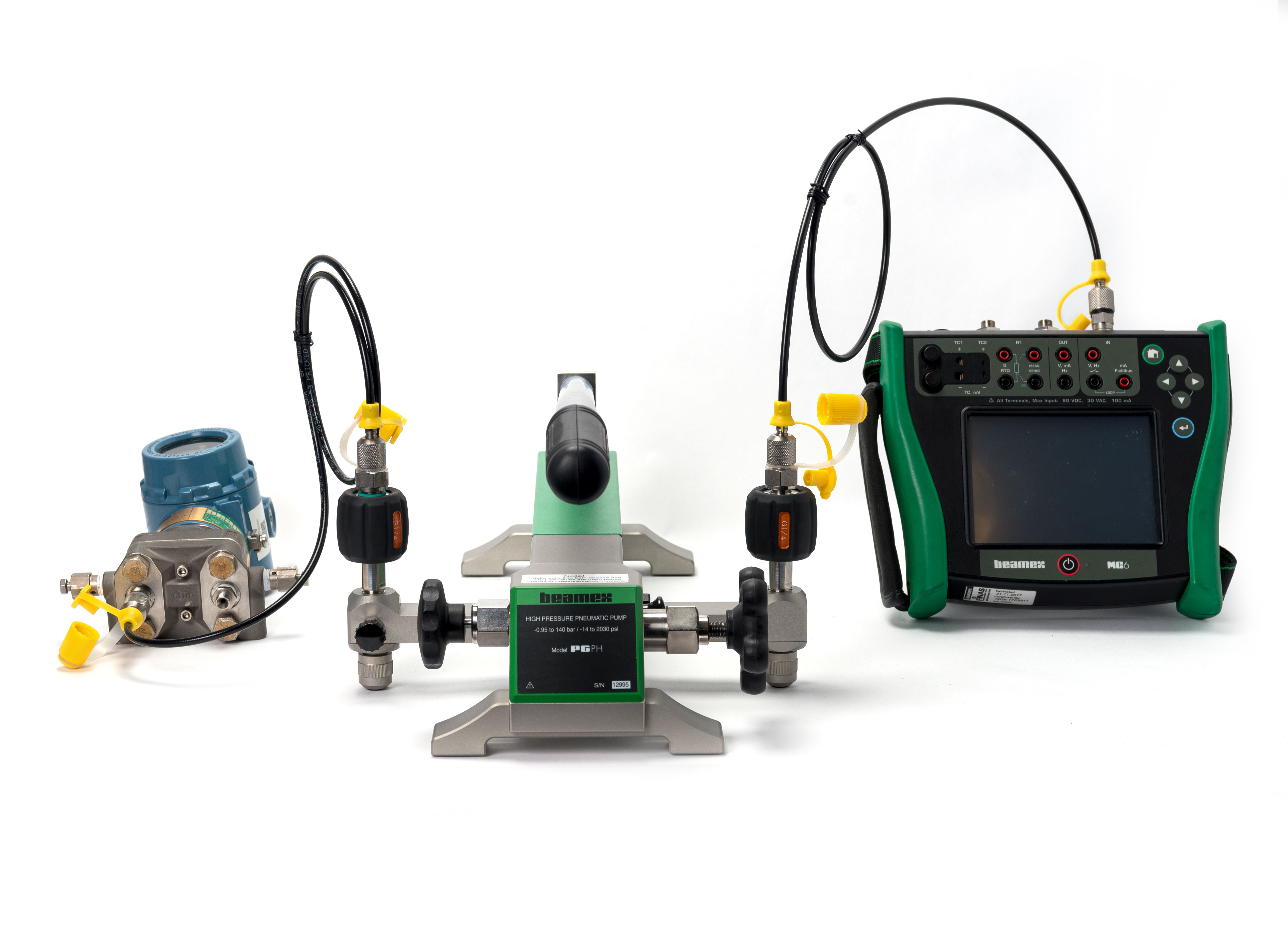
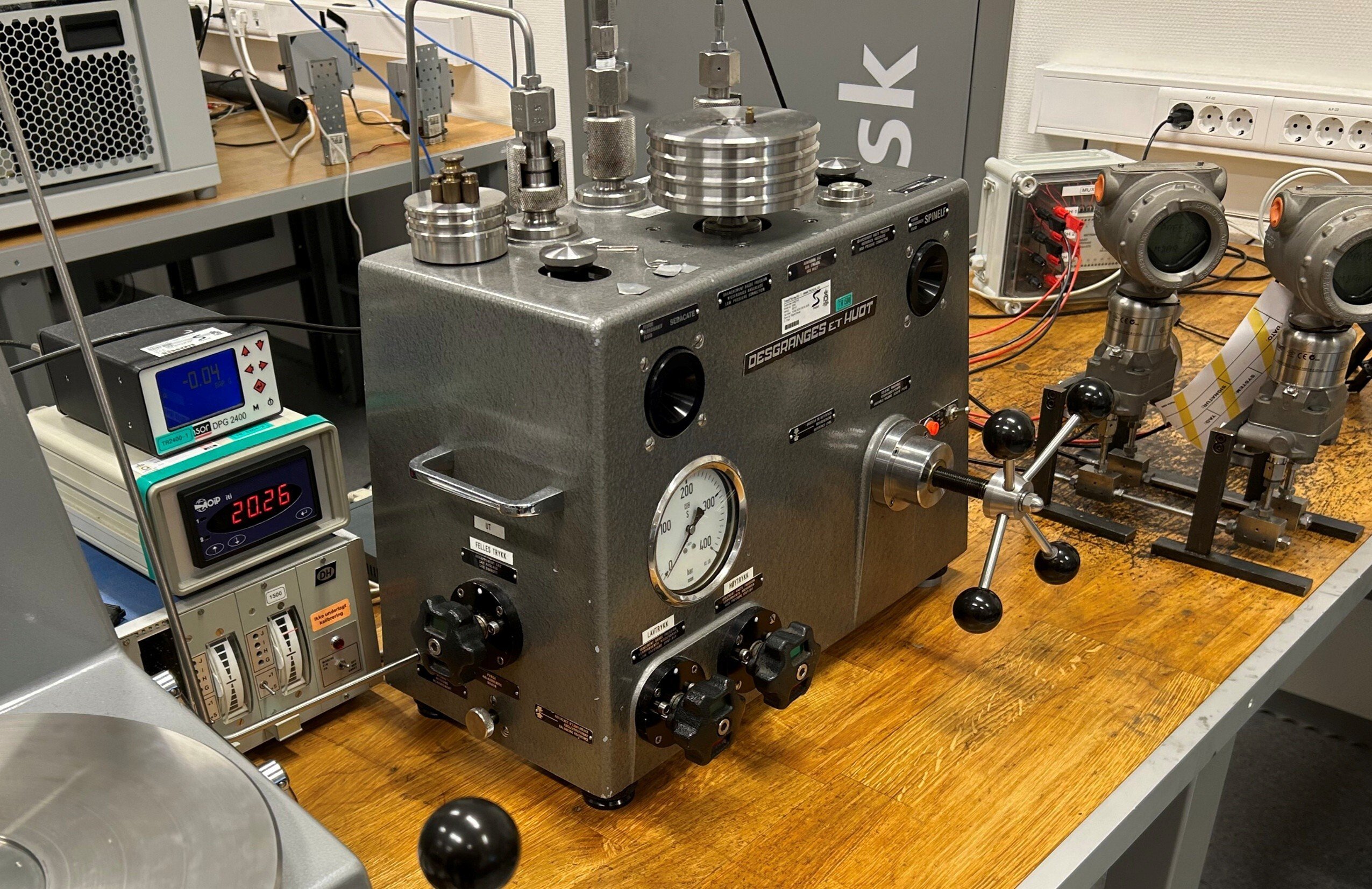
9 - Generating pressure
To calibrate a pressure gauge, you need to source the pressure applied to the gauge.
There are different ways to do that: you can use a pressure hand pump, a pressure regulator with a bottle or even a dead weight tester. A dead weight tester will provide a very accurate pressure and you don’t need a separate calibrator to measure the pressure, but dead weight tester is expensive, not very mobile, requires a lot of attention to use and it is sensitive to dirt.
It is more common to use a pressure calibration hand pump to generate pressure and an accurate pressure measurement device (calibrator) to measure the pressure. A pressure controller can also be used to supply the pressure.
10 - Pressurizing / exercising the gauge
Due to its mechanical structure, a pressure gauge will always have some friction in its movement, and may change its behavior over time, therefore you should exercise it before calibration. This is especially the case if the gauge has not been applied with pressure for a while. To exercise, supply the nominal max pressure and let it stay for a minute, then vent the pressure and wait a minute. You should repeat this process 2-3 times before starting to do the actual calibration cycle.
11 - Reading the pressure value (resolution)
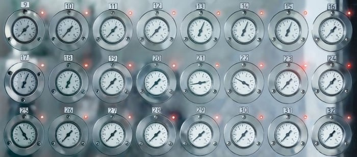
The scale in analog pressure gauges have limited readability. It has major and minor scale marks, but it is difficult to accurately read the pressure value when the indicator is in between the scale marks. It is much easier to see when the needle is exactly at a scale mark. Therefore, it is recommended to adjust the input pressure so that the needle is exactly at an indication mark, and then record the corresponding input pressure. If you just supply a certain accurate input pressure and then try to read the indicator, it will cause errors due to limited reading accuracy.
Also, it is important to look at the indication perpendicular to the gauge scale. Many accurate gauges have a reflecting mirror along the scale, behind the needle pointer. This mirror helps you read it, and you should read it so that the mirror reflection of the needle is exactly behind the actual needle. Then you know that you are looking perpendicular/straight at the gauge.
Picture: Left gauge in the below picture is difficult to read accurately as the indicator is between scale marks, while the right one is easy to read since the applied pressure is adjusted so that pointer is exactly on scale mark:

Picture: Many high accuracy pressure gauges are provided with a mirror along the scale, helping to view the gauge perpendicular, as the mirror image of the pointer is hidden behind the pointer, or with the help of the reflection of the pointer:

Remaining topics
To prevent this blog post coming way too long, please download the white paper and read all the 20 topics from that.
The remaining topics not covered here include:
12 - Number of calibration points
13 - Hysteresis (direction of calibration points)
14 - “Tapping” the gauge
15 - Number of calibration cycles (repeatability)
16 - Adjustment / correction
17 - Documentation – calibration certificate
18 - Environmental conditions
19 - Metrological traceability
20 - Uncertainty of calibration (TUR/TAR)
Please download related free white paper by clicking the below picture:
Pressure Calibration eLearning
Free eLearning course on industrial pressure calibration.
Master pressure calibration with this free comprehensive eLearning course from Beamex. Deepen your knowledge, pass the quiz, and earn your certificate!
Related resources
Beamex products suitable for pressure calibration, including pressure gauge calibration:
https://www.beamex.com/calibrators/pressure-calibrators/
An online tool for pressure unit conversion on Beamex web site: Pressure unit converter
Please check out our new electric pressure pump Beamex ePG:

Related blog posts:
- Why calibrate?
- How often should instruments be calibrated?
- Calibration uncertainty for dummies
- Pressure calibration basics – pressure types
- Pressure units and pressure unit conversion
- Metrological traceability in calibration
- What is a documenting calibrator and how do you benefit from using one?
Back to top ⇑


.jpg)


Discussion