
 When calibrating process instruments, there is more than one way to approach the task. While calibration is typically carried out by calibrating each instrument separately, many plants also use loop calibration to check the whole measurement loop end to end.
The challenge is that these two approaches answer different questions. Loop calibration focuses on the final measurement value used by the control system, while instrument calibration focuses on the accuracy and traceability of individual devices. Choosing the wrong approach for your situation can lead to unnecessary work, hidden risks, or gaps in documentation.
In this blog, we look at loop calibration versus instrument calibration from a practical point of view. We explain what a measurement loop means in this context, how the two calibration approaches differ, and where partial loop calibration fits in. We also discuss real-world considerations such as filtering, display resolution, error compensation, traceability, and compliance.
The goal is not to promote one method over the other, but to help you understand when each approach makes sense and how they can be combined as part of a smart calibration strategy.
Download a free pdf version of this article >>
Table of contents
-
How to choose between loop calibration and instrument calibration
-
Pros and cons of loop calibration and instrument calibration
- Expert insight: Why pharma prefers loop calibration
What do we mean by a “loop” in this article?
The term loop can mean different things in instrumentation depending on industry, role, and background. To avoid confusion, it’s worth defining what we mean by a loop.
For the purposes of this article a measurement loop means a set of instruments connected in series that together produce a single measurement value used by the control system or operators.
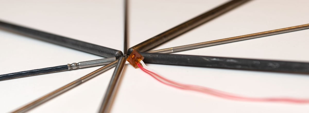
A typical example is a temperature measurement loop. It may consist of:
- a temperature sensor installed in the process,
- a temperature transmitter connected to the sensor,
- a local indicator,
- wiring from the field to the control system (PLC or DCS), and
- the scaled value displayed in the control room or operator interface.
Example of a measurement loop starting at the process sensor and ending at the final values shown on the control room display.
The same principle applies to other measured quantities, such as pressure, flow, or level. The loop starts at the sensor installed in the process and ends at the value that is used for monitoring, control, alarms, or reporting.
In other words, the loop is not a single device – it is the entire signal chain, from the physical process all the way to the final displayed or used measurement value.
Two approaches to calibrating a measurement loop
When it comes to calibrating a measurement loop, there are two fundamentally different approaches. Both are widely used in industry, and both have their place.
The difference is not about tools or standards, but about what you choose to calibrate.
One approach focuses on the final measurement result that the control system uses, while the other focuses on the individual instruments that make up the measurement loop.
Calibrating the loop end to end
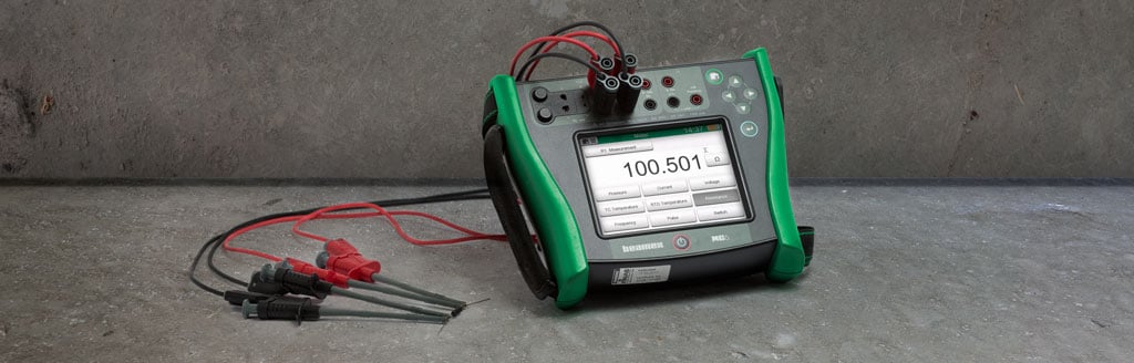
In a loop calibration, the entire measurement loop is calibrated as one functional chain. An accurate reference signal is applied to the first element of the loop, typically the sensor or transmitter input, and the reference is then compared to the final value displayed on the control room display.
If the displayed value is within the accepted tolerance, the loop is considered calibrated for its intended purpose, without the need to adjust or disconnect individual instruments.
This approach answers a very practical question:
Does the measurement value used by the control system represent the process accurately enough?
Calibrating instruments individually
In traditional instrument calibration, each device in the measurement loop is calibrated separately.
This typically means calibrating:
- the sensor,
- the transmitter,
- any local indicators, and
- the control system input or scaling.
Each of these is performed as an individual calibration task, often using different reference signals and methods.
This ensures that every individual instrument in the loop is calibrated within its specified accuracy requirements.
This approach answers a different question: Is each individual instrument performing within its specified accuracy limits?
Same loop, different focus
Both approaches target the same measurement loop, but from different perspectives.
Loop calibration focuses on the performance of the measurement loop as a whole, while instrument calibration focuses on the performance of each building block of the measurement loop.
In practice, calibration strategies often combine both approaches. The key question is not which method is “right”, but when each approach makes sense.
Loop calibration in practice
In practice, loop calibration means working with the measurement loop as a single functional entity rather than as individual instruments. The focus is on how the loop behaves under real operating conditions, from applying the reference signal in the field to observing the resulting value from the control system.
Once you understand the basic principle of loop calibration, the practical details become important. These include how the loop responds over time, how readings are taken, and how field and control room activities are coordinated.
Timing, filtering, and patience
When calibrating a loop, it is important not to rush the readings.
Many measurement loops include filtering or damping, either in the transmitter or in the control system, to prevent the system from reacting too quickly to process fluctuations. As a result, the final displayed value may respond slowly to changes in the input signal.
If reference values are applied and read too quickly, this delay can easily appear as a calibration error, even though the loop itself is functioning correctly.
For example, if pressure is applied to a pressure measurement loop and the control room value is read immediately, the displayed value may not yet have settled due to filtering. In other words, taking readings too early can lead to incorrect conclusions.
In addition, control room displays are often intentionally configured with a limited number of decimals – or even rounded to whole numbers – to make the values easier for operators to read and use. While this is perfectly appropriate for normal operation, it can limit the usefulness of the displayed value for calibration purposes.
When performing loop calibration, it is often necessary to temporarily increase the number of displayed decimals or access a more detailed diagnostic view in the control system. Without sufficient resolution in the displayed value, it can be difficult or impossible to determine whether the loop is really within the required calibration tolerance.
Reading input and output at the same time
In loop calibration, the loop input and loop output are often physically far apart. The reference signal is typically generated in the field, while the final value is read in the control room.
Because of this, loop calibration is commonly performed by two people: one in the field applying and reading the reference input and one in the control room reading the displayed value.
It is important that these readings are taken at the same time. This becomes especially critical when:
- the input signal changes slowly over time (for example pressure decay),
- the loop includes filtering or time delays, or
- the process conditions are not perfectly stable.
If the input changes while the output is delayed, it can be difficult to establish a stable relationship between the two unless readings are properly synchronized.
What happens if the loop fails?
If a loop calibration result is within tolerance, there is usually no need to calibrate the individual instruments in the loop.
However, if the loop error exceeds the accepted limits, loop calibration alone is no longer sufficient. In that case, the next step is to calibrate the individual instruments in the loop to identify which component or components are contributing most to the error.
Loop calibration can therefore be seen as both an efficient calibration method and a starting point for performing diagnostics.
 A typical loop calibration setup where a reference signal is applied in the field and the resulting value is observed in the control room.
Instrument calibration in practice
In instrument calibration, each device in the measurement loop is calibrated separately using an appropriate reference signal.
This typically means calibrating the sensor, transmitter, local indicators, and the control system input as individual tasks rather than as one end-to-end measurement.
Calibrating individual instruments
Instrument calibration focuses on the performance of each instrument on its own. The reference signal is applied directly to the instrument under test and the output is compared to the reference.
For example:
- a temperature sensor is calibrated using a temperature block as heat source and a reference sensor and measuring the sensor output signal
- a transmitter is calibrated by simulating a sensor signal or applying a known input and then measuring the output signal (typically mA)
- a local indicator is calibrated against a known reference signal depending on the type of indicator
- a control system input is calibrated by applying an accurate electrical signal and verifying that the reading is correct.
With instrument calibration, each instrument is evaluated against its own acceptance criteria and tolerance.
Accuracy and traceability
One of the key strengths of instrument calibration is that it provides clear traceability for each individual device. Each instrument can be checked against its specified accuracy requirements, independent of the rest of the loop.
This is particularly important when:
- tight accuracy requirements apply,
- individual instruments have different calibration intervals, or
- documentation and traceability are critical, such as in regulated or quality-critical environments.
Practical implications in the field
Calibrating instruments individually often requires disconnecting instruments from the loop. This can increase the amount of work compared to loop calibration, especially in loops with several devices.
Disconnecting and reconnecting instruments also introduces practical risks, such as:
- wiring mistakes,
- poor connections, or
- unintentional configuration changes.
On the other hand, instrument calibration can often be performed by a single technician and does not usually require access to the control room display during the calibration process.
When instrument calibration becomes necessary
Instrument calibration is typically required if:
- a loop calibration fails and the source of error needs to be identified,
- an individual instrument has been replaced or repaired, or
- the measurement is highly critical and each component must meet its own accuracy requirement and calibration interval.
In these cases, calibrating the loop alone is not sufficient because doing so will not show how individual instruments are performing.
Verifying a loop after instrument calibration
It is good practice to perform a quick loop check after an instrument has been calibrated and reinstalled in the loop.
A loop check does not need to be a full loop calibration. In many cases it is sufficient to apply a known input signal at one point in the loop and confirm that the corresponding value is correctly received and displayed by the control system. This helps to verify that:
- wiring and connections are correct,
- signal paths are intact, and
- scaling and configuration still match the intended setup.
For the most critical measurements, a full loop calibration can be performed after all individual instruments have been calibrated. This provides the highest level of confidence that the entire measurement loop is functioning correctly.
Even when a full loop calibration is not required, performing at least a simple loop check after instrument calibration helps catch installation or connection issues early and ensures that the loop is working as intended before it is returned to operation.
Partial loop calibration
Calibration is not always a choice between calibrating the entire loop end to end or calibrating every instrument separately. In many real-world situations, a partial loop calibration provides a practical and efficient alternative.
In partial loop calibration, several instruments in the measurement loop are calibrated together but the loop is not calibrated end to end.
A partial loop can include, for example:
- a transmitter and the control system input,
- a sensor and transmitter without the control system input,
- a transmitter, the wiring, and a local indicator.
The exact scope depends on what parts of the loop are accessible, what parts are critical, and what the purpose of the calibration is.
When to use partial loop calibration
Partial loop calibration is often used when:
- calibrating the full loop end to end is not practical,
- access to the process sensor is limited or difficult,
- the control room display is not easily accessible,
- only certain parts of the loop are known or suspected to contribute to error.
Partial loop calibration can also be a deliberate strategy when different parts of the loop have different calibration intervals.
The benefits and limitations of partial loop calibration
Partial loop calibration can significantly reduce the amount of effort compared to calibrating every instrument separately, while still providing better confidence than calibrating individual devices.
However, because the loop is not tested end to end, partial loop calibration does not fully verify the final measurement value used by the control system. Any parts of the loop that are excluded from the calibration may still contribute to overall measurement error.
A pragmatic approach
In practice, partial loop calibration is often used as part of a broader calibration strategy combined with:
- periodic full loop calibration,
- instrument calibration triggered by failures or replacements, and
- risk-based calibration planning.
This pragmatic approach allows organizations to balance accuracy, effort, and operational constraints.
Error compensation and hidden risks
One important aspect of loop calibration that is easy to overlook is error compensation between different instruments in the loop.
It is possible for two or more instruments in a measurement loop to have errors that point in opposite directions. These errors may partially or even fully cancel each other out. For example, a sensor may be reading slightly low while a transmitter or control system input is reading slightly high. When these errors are combined in the loop, the final displayed value may appear to be well within tolerance.
From a loop calibration point of view the loop looks accurate and passes the calibration, and from an operational point of view the measurement result used by the control system is acceptable. However, loop calibration alone will not show that individual instruments are already drifting.
Why error compensation is a risk and what it means in practice
Error compensation is a risk when something in the loop changes. If one instrument is replaced, repaired, or recalibrated, the previously compensating error may disappear. Once that happens, the remaining error in the loop becomes visible, and the loop may suddenly fail calibration or behave differently than expected.
This can come as a surprise if the loop has historically passed loop calibration without issues. Cases like this do not mean that loop calibration is wrong or unsafe, but they do show that loop calibration should be understood for what it is: a calibration of the final measurement result, not a guarantee that every individual instrument is perfectly accurate.
For this reason, loop calibration is often sufficient for ongoing operation, but instrument calibration becomes important after changes in the loop, and especially after replacing one or more instruments.
A practical calibration strategy recognizes this kind of behavior and allows organizations to plan accordingly. Loop calibration can be used to efficiently confirm correct loop performance, while instrument calibration is used selectively to manage long-term accuracy and changes in the loop.
Understanding error compensation helps avoid false confidence and supports better decision making about when deeper calibration work is needed.
How to choose between loop calibration and instrument calibration
Choosing between loop calibration and instrument calibration is not about choosing one method over the other. In practice, the choice depends on the purpose of the measurement, the required accuracy, and the risks associated with incorrect measurements.
The most important question to ask is not how to calibrate, but what needs to be ensured.
Traceability, documentation, and compliance
For critical instruments, calibration is often not only a technical task but also a documentation requirement.
In cases where a dedicated calibration certificate is required for traceability, audits, or regulatory compliance, instrument calibration is typically necessary. Calibrating the loop end to end may confirm correct loop performance, but it does not usually provide individual calibration records for each instrument.
This is especially relevant in regulated environments, where calibration documentation must clearly show which instrument was calibrated against which reference and what the result was.
In such cases, instrument calibration is required regardless of whether or not loop calibration would be technically sufficient.
Required accuracy and tolerance
The tighter the required tolerance, the more important it becomes to understand the performance of individual instruments.
If the allowed error is relatively large compared to the accuracy of the instruments in the loop, loop calibration is often adequate. When tolerances are tight, instrument calibration is usually required to identify and correct small errors in individual components.
Combining loop calibration and instrument calibration
In many plants, the most effective calibration strategy combines:
- loop calibration for efficient confirmation of loop performance,
- instrument calibration for critical loops or after changes, and
- partial loop calibration where full end-to-end testing is not practical.
Rather than following a fixed rule, the goal is to apply the right method at the right time.
Pros and cons of loop calibration and instrument calibration
Both loop calibration and instrument calibration have clear advantages and limitations. Understanding them will help you to choose the most suitable method for a given situation.
Loop calibration
Pros
- Calibrates the entire measurement loop end to end in one go
- Confirms the accuracy of the value used by the control system
- Eliminates the need to disconnect individual instruments during calibration
- Can be an efficient way to calibrate several similar loops
Cons
- Often requires two people, one in the field and one in the control room
- Does not provide individual calibration results or certificates for each instrument
- May hide individual instrument errors due to error compensation
- Not always practical if the sensor cannot be accessed or simulated
Instrument calibration
Pros
- Provides clear calibration results and traceability for each individual instrument
- Provides individual calibration certificate for each instrument
- Can often be performed by a single technician
- Makes it easier to identify and correct errors in specific devices
- Allows different calibration intervals for different instruments in the loop
Cons
- Requires more work when a loop includes several instruments
- Often involves disconnecting and reconnecting instruments, which increases the risk of wiring or configuration errors
- Does not validate the performance of the complete loop
Expert insight: Why pharma prefers loop calibration
We asked a calibration expert from the pharmaceutical industry to share his perspective on loop calibration.
 Josh Jesse, Global Calibration SME at a Pharma CDMO, explains:
“In a risk-based validated GMP pharmaceutical environment, the objective is to demonstrate that systems perform as intended in their installed condition. For that reason, I consistently prefer and recommend loop calibration over individual instrument calibration in most cases, because it confirms end‑to‑end performance of the control loop under actual operating conditions rather than relying on assumed correctness of individual components.
Of course, a robust risk assessment upon initial equipment review can assist in deciding what is best for each individual calibration task.”
Risk-based calibration approach
Not all components in a measurement loop are equally exposed to drift or failure. Some instruments operate in harsher conditions or experience greater process stress than others.
A risk-based calibration approach focuses calibration effort where the risk is highest. Instead of calibrating the entire loop at the same interval, individual instruments that are more likely to drift can be calibrated more frequently.
For example, a process temperature sensor exposed to large temperature changes may require more frequent calibration than the rest of the loop, while full loop calibration is performed less often. This approach helps use calibration resources efficiently while maintaining confidence in the overall measurement.
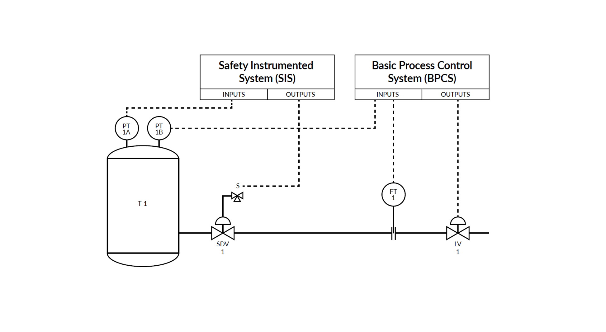
Safety Instrumented Systems (SIS) and loop calibration
One common application where loop calibration is widely used in the process industry is Safety Instrumented Systems (SIS).
In SIS applications, the main concern is whether the entire safety loop works correctly end to end, not just how individual instruments perform on their own. For this reason, SIS measurement loops are often tested and verified by applying a reference signal in the field and observing the response through the complete signal chain, including the logic solver and final indication or action. This makes loop-style calibration and testing a natural and practical approach for safety-critical loops.
Loop calibration helps verify that signal transmission, scaling, configuration, and system response behave as intended under real conditions. However, it does not replace instrument calibration. Individual sensors and transmitters in SIS loops are still typically calibrated separately to ensure long-term accuracy, traceability, and compliance.
For a more detailed discussion on SIS, proof testing, and calibration practices specific to safety applications, see our related blog: Understanding Safety Instrumented Systems (SIS) and the importance of calibration >>
Digital signals and loop calibration
Modern measurement loops increasingly use digital communication and smart instruments. Compared to traditional analog loops, digital signals typically involve fewer analog-to-digital and digital-to-analog conversions in the signal chain.
As a result, digital loops can have fewer sources of error than analog loops, as well as fewer elements that require traditional calibration.
However, even in digital systems the basic principle of calibration does not change. The measurement loop still starts at the sensor in the process and ends at the value used by the control system or operator. Digital systems may shift where errors occur, but they do not remove the need to think end to end when choosing a calibration strategy.
Loop calibration is still relevant because it confirms that the final measurement result – including digital processing, scaling, and configuration – is correct. Instrument calibration, on the other hand, is a way to ensure that individual devices, sensors, and internal measurement functions perform as intended.
Conclusion
Loop calibration and instrument calibration are not competing methods. They are complementary approaches that serve different purposes in maintaining reliable and accurate measurements.
Loop calibration provides an efficient way to confirm that the measurement value used by the control system is accurate enough for its intended purpose. Instrument calibration provides confidence, traceability, and detailed insight into the performance of individual devices.
In practice, the most effective calibration strategies combine the two approaches. Loop calibration can be used to efficiently verify overall loop performance, while instrument calibration is applied where accuracy, traceability, or changes in the loop require deeper analysis.
By understanding the strengths and limitations of each method, organizations can make better calibration decisions, reduce unnecessary work, and maintain confidence in their measurement systems.
Download free white paper
Click the image below to download a pdf white paper of this article.

The Beamex perspective: supporting different calibration approaches
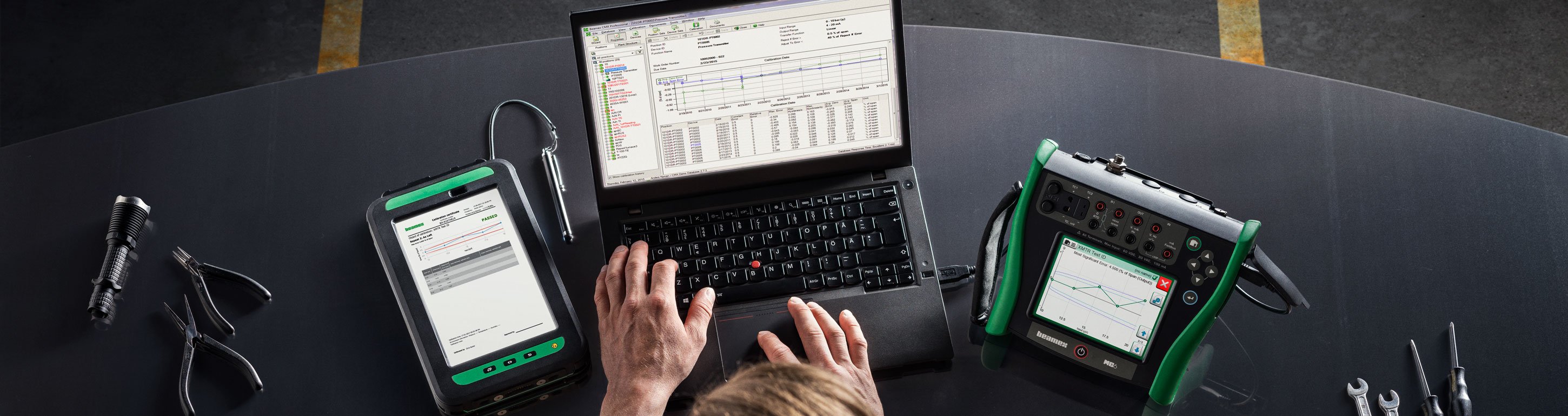
The Beamex calibration ecosystem is designed to support a flexible approach to calibration. Whether you are calibrating individual instruments, partial loops, or full measurement loops end to end, Beamex solutions help ensure accurate measurements, efficient work processes, and reliable documentation.
Beamex calibration equipment allows you to generate and measure accurate reference signals in the field, while Beamex calibration management software helps you to plan calibration work, document the results, and maintain traceability. Together, Beamex equipment and software allows you to apply the calibration method that best fits each situation, without compromising accuracy or compliance.
But choosing the right calibration approach is not always straightforward. Factors such as process criticality, accuracy requirements, documentation needs, and available resources all play a role. Beamex experts can work with you to help define calibration strategies that are practical, efficient, and aligned with real operational needs.
We continuously develop our solutions in close cooperation with customers, following changes in technology, working practices, and system connectivity. As calibration work evolves, our goal remains the same: to make calibration more efficient while maintaining accuracy, traceability, and confidence in measurement results.
Want to discuss what works best for you?
If you would like to discuss loop calibration, instrument calibration, or how to combine these two different approaches in your environment, contact our experts to explore what makes the most sense for your processes.


.png)


.jpg)

Discussion