In some earlier blog posts, I have discussed temperature calibration and calibration uncertainty. This time I will be covering the different uncertainty components that you should take into account when you make a temperature calibration using a temperature dry block.
Making a temperature calibration using a dry block seems like a pretty simple and straight forward thing to do, however there are many possible sources for uncertainty and error that should be considered. Often the biggest uncertainties may come from the procedure on how the calibration is done, not necessarily from the specifications of the components.
Let’s turn the heat on!
If you just want to download this article as a free pdf file, please click the below button:

Table of contents
- What is a dry block?
- So, it's not a bath?
- EURAMET Guidelines
- Uncertainty Components
- Internal or External reference sensor
- 1. Internal reference sensor
- 2. External reference sensor
- 3. Axial temperature homogeneity
- 4. Temperature difference between the borings
- 5. Influence of loading
- 6. Stability over time
- 7. Don't be in a hurry
- Summary
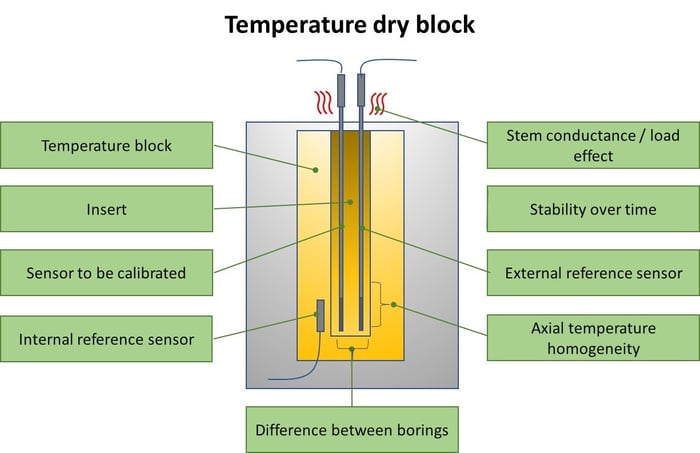
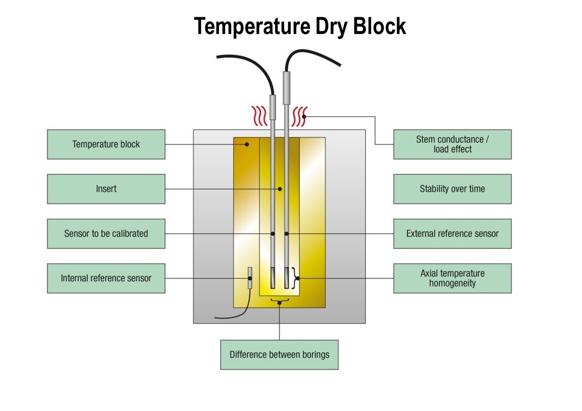
What is a “dry block”?
Let’s start anyhow by discussing what I mean with a “temperature dry block” in the article.
A temperature dry block is sometimes also called a dry-well or a temperature calibrator.
It is a device that can be heated and/or cooled to different temperature values, and as the name hints, it is used dry, without any liquids.
A dry block typically has a removable insert (or sleeve) that has suitable holes/borings for inserting temperature sensors into.
The dry block typically has its own internal measurement for the temperature, or you may use an external reference temperature sensor that you will insert into one of the holes.
Commonly a dry block has interchangeable inserts, so you may have several inserts, each being drilled with different holes, to suit for calibration of different sized temperature sensors.
It is very important in a dry block that the hole for the temperature sensor is sufficiently tight to enable low thermal resistance between the sensor and the insert. In too loose of a boring, the sensor stabilizes slowly or may not reach the temperature of the insert at all due to stem conduction.
Commonly, you would insert a temperature sensor in the dry block to be calibrated or calibrate a temperature loop where the temperature sensor is the first component in the loop.
The main benefits of a dry block are that it is easy to carry out in the field and there is no hot fluid that would spill when you carry it around. Also, a dry block will not contaminate the temperate sensors being calibrated.
Dry blocks are almost always used dry. In some very rare cases you may use some heat transfer fluids or pastes. In most cases you may damage the dry block if you use liquids.
Using oil or pastes also cause a potential health and fire risk if later used in temperatures higher than for example a flash point of the foreign substance. A 660 °C dry block that has silicon oil absorbed into its insulation may look neat outside, but it will blow out a noxious fumes when heated up. Calibration labs everywhere are probably more familiar with this than they would like to be…
As drawbacks for dry blocks, we could consider lower accuracy/stability than with a liquid bath and more difficult to calibrate very short and odd shaped sensors.
So, it’s not a “bath”?
Nope, I said “dry block”, didn’t I … ;-)
There are also temperature baths available, having liquid inside. The liquid is heated/cooled and the temperature sensors to be calibrated are inserted into the liquid. Liquid is also being stirred to get even temperature distribution in the liquid.
There are also some combinations of dry block and liquid bath, these are devices that typically have separate dry inserts and separate liquid inserts.
The main benefits of a liquid bath are the better temperature homogeneity and stability and suitability for short and odd shaped sensors.
While the drawbacks of liquid bath are the bigger size, heavier weight, working with hot liquids, poorer portability and they’re often slower than dry blocks.
Anyhow, in this article we focus on the temperature dry blocks, so let’s get back to them.
EURAMET Guidelines
Let’s take a quick look into Euramet guides before we proceed. And yes, it is very relevant for this topic.
EURAMET is the Regional Metrology Organisation (RMO) of Europe. They coordinate the cooperation of National Metrology Institutes (NMI) in Europe. More on Euramet at https://www.euramet.org/
Euramet has also published many informative guidelines for various calibrations.
The one that I would like to mention here is the one dedicated for temperature dry block calibration: EURAMET Calibration Guide No. 13, Version 4.0 (09/2017), titled “Guidelines on the Calibration of Temperature Block Calibrators”.
The previous version 3.0 was published in 2015. First version was published in 2007. That guideline was earlier called EA-10/13, so you may run into that name too.
The guideline defines a normative way to calibrate temperature dry blocks. Many manufacturers use the guideline when calibrating dry blocks and when giving specifications for their dry blocks.
To highlight some of the contents of the most recent version 4.0, it includes:
Scope
Calibration capability
Characterisation
- Axial homogeneity
- Temperature difference between borings
- Effects of loading
- Stability over time
- Heat conduction
Calibration
- Measurements
- Uncertainties
Reporting results
Examples
You can download the Euramet guide pdf free here:
Guidelines on the Calibration of Temperature Block Calibrators
Uncertainty components
Let’s get into the actual uncertainty components. When you make a temperature calibration using a dry block, these are the things that cause uncertainty/error to the measurement results.
Internal or External reference sensor?
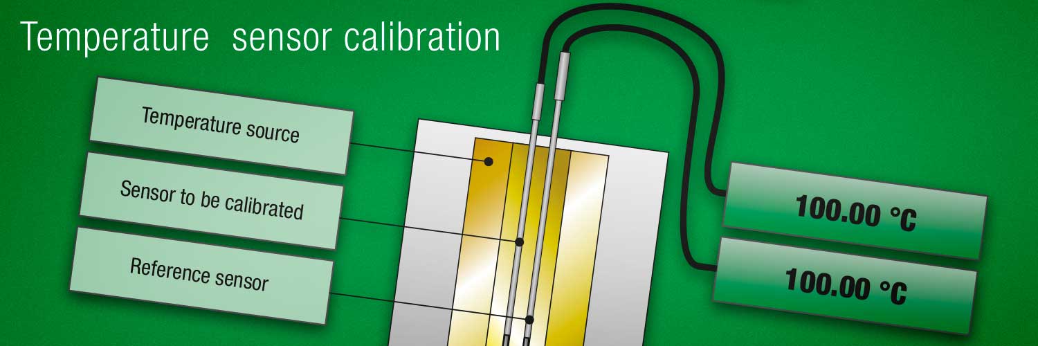
There are two principle ways to measure the true (correct) temperature of a dry block. One is to use the internal measurement using the internal reference sensor that is built in into the dry block, the other is to use an external reference sensor that is inserted into the insert boring/hole.
There are some fundamental differences between these two ways and they have a very different effect on the uncertainty, so let’s discuss these two options next:
1. Internal reference sensor
An internal reference sensor is permanently inserted into the metal block inside the dry block, it is typically close to the bottom part of the block and it is located in the metallic block surrounding the interchangeable insert.
So, this internal sensor does not directly measure the temperature of the insert, where you insert the sensors to be calibrated, but it measures the temperature of the surrounding block. Since there is always some thermal resistance between the block and the insert, this kind of measurement is not the most accurate one.
Especially when the temperature is changing, the block temperature normally changes faster than the insert temperature. If you make the calibration too quickly without waiting sufficient stabilization time, this will cause an error.
An internal reference sensor is anyhow pretty handy, as it is always readily inside the block, and you don’t need to reserve a dedicated hole in the insert for it.
The recalibration of the internal measurement is a bit difficult, as you need to send the whole dry block into recalibration.
An internal measurement sensor’s signal is naturally measured with an internal measurement circuit in the dry block and displayed in the block’s display. The measurement typically has an accuracy specification given. As discussed earlier, in practice this specification is only valid in stable conditions and does not include the uncertainties caused if the calibration is done too quickly or the sensors to be calibrated are not within the calibration zone at the bottom part of the insert, in a sufficiently tight boring.
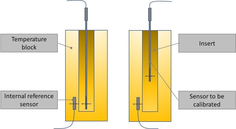
The above left side pictures illustrate how the internal reference sensor is typically located in the temperature block, while the sensor to be calibrated is inserted into the insert. If the sensor to be calibrated is long enough and reaches the bottom on the insert, the boring is tight enough, and we waited long enough for stabilization, we can get good calibration with little error.
In the right side picture we can see what happens if the sensor to be calibrated is too short to reach to the bottom of the insert. In this case, the internal reference sensor and the sensor to be calibrated are located at different heights and are measuring different temperatures, causing a big error to the calibration result .
2. External reference sensor
The other way is to use an external reference sensor. The idea here is that you insert a reference sensor into a suitable hole in the insert, while you enter the sensors to be calibrated in the other holes in the same insert.
As the external reference sensor is inserted into the same metal insert with the sensors to be calibrated, it can more precisely measure the same temperature as the sensors to be calibrated are measuring.
Ideally, the reference sensor would have similar thermal characteristics as the sensors to be calibrated (same size and thermal conductance). In that case, as the insert temperature changes, the external reference sensor and the sensor to be calibrated will more accurately follow the same temperature changes.
The external reference sensor naturally needs to be measured somehow. Often a dry block has internal measurement circuitry and a connection for the external reference sensor or you can use an external measurement device. For uncertainty, you need to consider the uncertainty of the reference sensor and the uncertainty of the measurement circuitry.
Using an accurate external reference sensor results in a more accurate calibration with smaller uncertainty (compared to using an internal reference sensor). So, it is highly recommended if you want good accuracy (small uncertainty).
An external reference sensor also promotes reliability. If the internal and external sensor readings differ a lot, it’s a warning signal to the user that something is probably wrong and the measurements may not be trustworthy.
For recalibration, in the case of an external reference sensor, you can send just the reference sensor for recalibration, not the whole dry block. In that case, you naturally will not have the dry block’s functionalities being checked (and adjusted if necessary), like the axial temperature homogeneity, for example.
If you don’t send the dry block for calibration, be sure to measure and record the axial gradient regularly yourself, as it’s typically the biggest uncertainty component also when the external reference sensor is used. Otherwise a strict auditor may profoundly question the traceability your measurements.
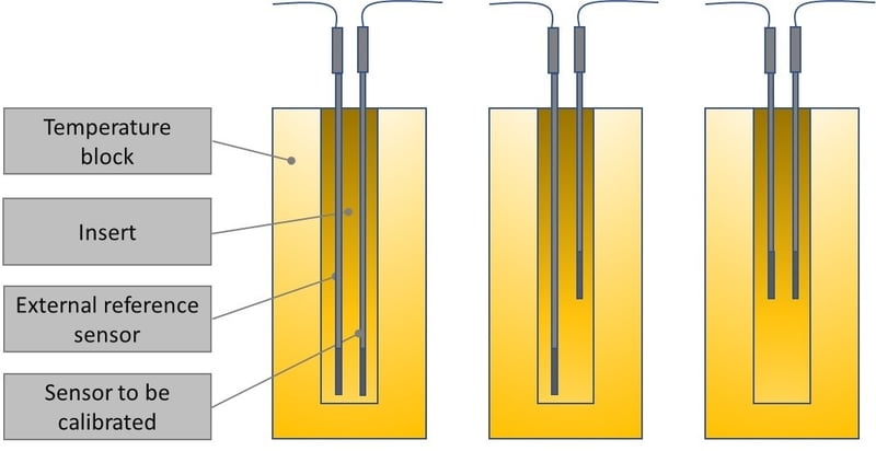
The above picture illustrate how the external reference sensor and the DUT (Device Under Test) sensor are both located in the insert. The first picture shows the case when both sensors reach the bottom of the insert, resulting in best calibration results.
The second picture shows what happens if the reference sensor and DUT sensor are at different depth. This will cause a big temperature difference between the two sensors and will result in error in calibration.
The third picture shows an example where the DUT sensor is short, and the reference sensor has been correctly positioned in the same depth as the DUT sensor. With this you can get the best possible calibration result, although the homogeneity of the insert is not very good at the upper part of the insert.
So, if the sensors are located at different heights, that will cause additional error, but using an external reference sensor the error is still anyhow typically smaller than when calibrating a short sensor using the internal reference sensor.
3. Axial temperature homogeneity
Axial homogeneity (or axial uniformity) refers to the difference in temperature along the vertical length of the boring in the insert.
For example, the temperature may be slightly different in the very bottom of the boring in the insert, compared to the temperature a little higher in the boring.
Typically, the temperature will be different in the very top of the insert, as the temperature is leaking to the environment, if the block’s temperature is very different than the environmental temperature.
Some temperature sensors have the actual measurement element being shorter and some longer. Also, some have the element closer to the tip than others. To assure that different sensors are in the same temperature, the homogenic zone in the bottom of the block’s insert should be long enough. Typically, the specified area is 40 to 60 mm.
A dry block should have sufficient area in the insert bottom within which the temperature homogeneity is specified. During a calibration of the block, this may be calibrated by using two high-accuracy reference sensors at different heights or using a sensor with a short sensing element that is gradually lifted higher from the bottom. This sort of short sensing element sensor needs to be stable but does not necessarily be even calibrated because it’s used just for measuring temperature difference at different heights. If needed, the axial temperature gradient can typically be adjusted in a dry block.
If you have a short (sanitary) temperature sensor that does not reach all the way to the bottom of the boring in the insert, then things will get a bit more complicated. In that case, the internal reference measurement in the dry block cannot really be used, as is typically in the bottom of the block. An external reference sensor should be used and it should have the center of the measurement zone inserted as deep as the center of the measurement zone of the short sensor to be calibrated.
Often, this means that a dedicated short reference sensor should be used, and inserted into the same depth as the short sensor to be calibrated. It gets even more difficult if the short sensor to be calibrated has a large flange as that will soak up temperature from the sensor.
Summary - During the calibration you should ensure that your reference sensor is inserted to the same depth as the sensor(s) to be calibrated. If you know the lengths and the locations of the sensing elements, try to align the centers horizontally. If that is not possible, then you need to estimate the error caused by that. You should use an external temperature sensor, if the accuracy requirements of the calibration are higher, or if the sensor to be calibrated is not long enough to reach the bottom on the insert hole.
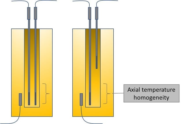
The above picture illustrate what the “axial temperature homogeneity” means. Typically, a dry block has a specified area in the bottom that has a homogenic temperature, but as you start to lift the sensor to be calibrated higher, it will not be in the same temperature anymore.
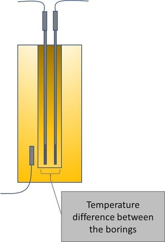
4. Temperature difference between the borings
As the title hints, the temperature difference between the borings, sometimes referred as “radial uniformity”, is the temperature difference between each boring (hole) in the insert. Although the insert is made of metal compounds and has a good thermal conductivity, there can still be a small difference between the borings, especially the opposite ones.
In practice, when you have two sensors in the insert installed in the different borings, there can be a small temperature difference between them.
The difference can be caused by the insert touching the block more on one side or the insert being loaded unequally (more sensors on one side, or thicker sensors in one side than on the other side). Of course, the heaters and Peltier elements, located on different sides, have their tolerances too.
The temperature difference between the borings in normally relatively small in practice.
Summary – the specification of the temperature difference between borings should be taken into account.
5. Influence of loading
There is always some heat conducted through the sensors to the environment (stem conductance) if the block’s temperature differs from the environmental temperature.
If there are several sensors installed in the insert, there will be more temperature “leaking” to the environment. Also, the thicker the sensors are, the more temperature leakage there will be.
The bigger the temperature difference between the insert and the environment temperature, the bigger the leakage will be.
For example, if you have the dry block at high temperature, this temperature leakage will cause the insert to cool down because of the loading. The top of the insert will lose more temperature than the bottom of the insert and the top becomes cooler.
The deeper the insert is, the less loading effect there will be. Also, some dry blocks have two or more heating/cooling zones: one in the bottom, one in center and one in the top of the block. This will help to compensate the loading effect (e.g. the top heating can heat more to compensate the top of the insert to cool down).
If you use the internal reference measurement of the dry block, there will typically be a larger error since the internal reference is not in the insert but is in the bottom of the surrounding block. Therefore, the internal reference sensor does not see this effect of loading very well.
An external reference sensor can better see the effect of loading, as it is in the insert and it will also have the same change in the temperature. The error caused by the loading effect is much smaller when external reference sensors is used (compared to using internal reference sensor), and the results are better.
Summary – check out the loading effect of your dry block in your application (how many sensors, which type of sensor) and use that as one uncertainty component.
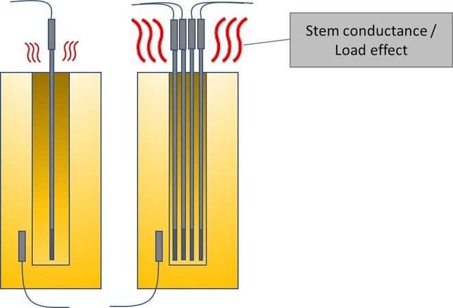
The above pictures illustrate the stem conductance caused by the sensors leaking the temperature to the environment. In the second picture there are several sensors inserted, so the stem conductance/leakage is larger.
6. Stability over time
Stability over time describes how well the temperature remains stable over a longer period. The temperature needs to be stable for certain time, as the different sensors may have different thermal characteristics and it takes different time for different sensors to stabilize. If the temperature is constantly creeping up and down, the different sensors may read different temperatures.
In case there is some fluctuation in the temperature, an external reference sensor will anyhow result in more accurate results, compared to the use of an internal reference sensor.
Often a dry block manufacturer has given a stability specification, for example for a 30 minute period.
7. Don’t be in a hurry!
It’s good to remember the fact that a temperature sensor will always measure only its own temperature. So, it does not measure the temperature where it is installed, but it will measure its own temperature.
Also, temperature changes pretty slowly and it takes some time before all parts of the system have stabilized to the same temperature, i.e. system has reached equilibrium.
If you make a temperature calibration with a dry block too fast, that will be the biggest source of uncertainty!
So, get to know your system and the sensors you calibrate and experiment to see how long time is enough for sufficient stabilization.
Especially if you use the internal reference sensor, it will reach the set temperature much faster than the sensors to be calibrated located in the insert. That is because the internal sensor is in the block that is heated/cooled, and the sensors to be calibrated are in the insert. Taking the results too soon can cause a big error.
In case of an external reference sensor, the need for stabilization depends on how different your reference sensor is compared to your sensors to be calibrated. If they have different diameter, they will most likely have different stabilization time. Anyhow, using an external reference sensor will be much more accurate than internal one, in case you don’t wait long enough for stabilization.
Often a dry block will have a stability indicator, but that may be measuring the stability of the internal reference sensors, so don’t trust only on that one.
Summary – shortly, if you do the temperature calibration too fast, the results will be terrible.
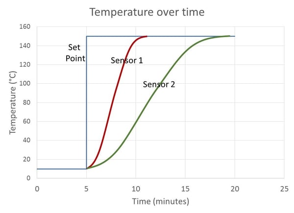
The above picture illustrates an (exaggerated) example where the temperature set point has been first 10°C and at the 5 minutes mark it has been changed to 150°C (blue line represents the set point).
There have been two sensors in the dry block – a reference sensor and a sensor to be calibrated.
We can see that the Sensor 1 (red line) changes much faster and reaches the final temperature at about 11 minutes point. The Sensor 2 (green line) changes much slower and it reaches the final temperature at around the 18 minutes mark.
The Sensor 1 is our reference sensor and the Sensor 2 is the sensor to be calibrated. We can see that if we read the temperatures too early at 10 minutes mark, we will get a huge error (about 85°C) in our results. Even if we take the readings at the 15 minutes mark, we still have around 20°C difference.
So, we should always make sure that we wait long enough to make sure that all sensors are stabilized to the new temperature, before we read the readings.
Summary
Making a temperature (sensor) calibration using a dry block seems pretty simple and straight forward thing to do. But there are anyhow many possible sources for uncertainty and error that should be taken into account.
Often the biggest uncertainties may come from the procedure on how the calibration is done, not necessarily from the specifications of the components.
For example, you may have an accurate dry block that has combined total uncertainty being 0.05°C and a high-quality reference sensor with uncertainty of 0.02°C. But anyhow calibrating a temperature sensor with these devices can have an uncertainty of several degrees, if it is not made properly.
That is one reason I don’t like the discussion of TAR (Test Accuracy Ratio) as it does not take into account all the uncertainties caused by the calibration procedure, it only uses the accuracy specifications.
I hope these considerations listed in the article help you to realize the possible sources of uncertainty and also how to minimize them.
If you want to download this article as a free pdf file, please click the below button:
Related blog posts
The main topics discussed in this article are temperature calibration and calibration uncertainty. Other blog posts on these topics, that you could be also interested in, are for example following:
- Measurement Uncertainty: Calibration uncertainty for dummies
- Metrological Traceability in Calibration – Are you traceable?
- Pt100 temperature sensor – useful things to know
- Thermocouple Cold (Reference) Junction Compensation
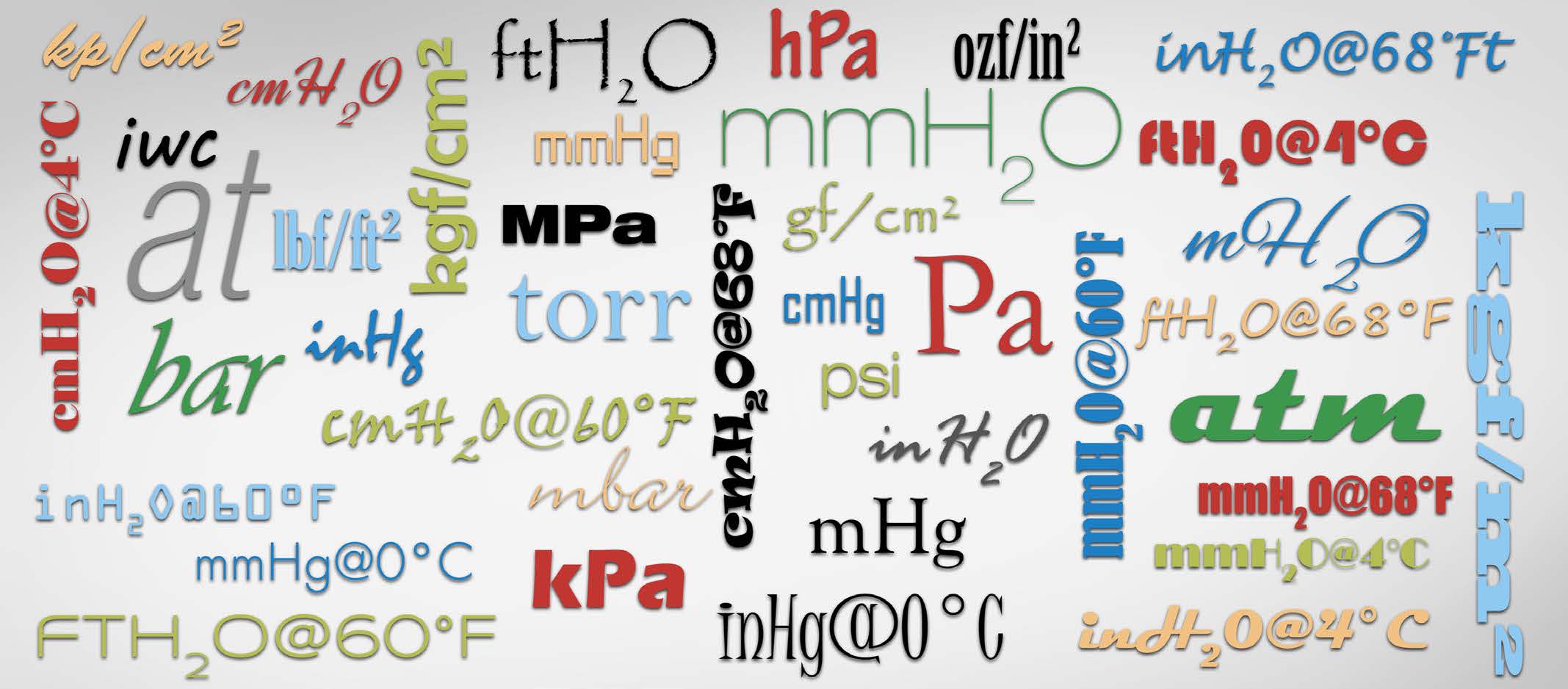
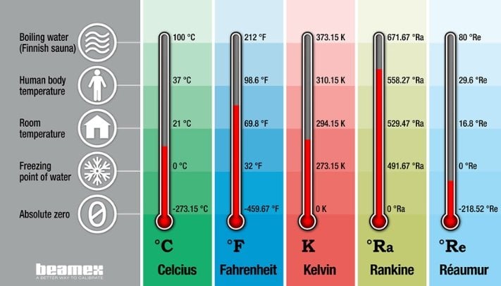
- Temperature units and temperature unit conversion
Beamex offering
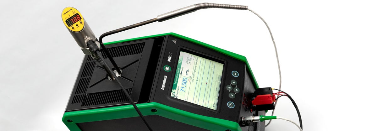
The Beamex MC6-T is a revolutionary temperature calibration tool, and it provides an excellent accuracy & uncertainty for temperature calibration. Please click the picture below to learn more:

Beamex offers also various other temperature calibration products, please check our offering in the below link:
Beamex temperature calibration products
Please subscribe & suggest topics
If you like these blog articles, please subscribe to this blog by entering your email address to the "Subscribe" box on the upper right-hand side. You will be notified by email when new articles are available, normally about once in month.
Also, please feel free to suggest good and interesting topics for new articles!
![How often should instruments be calibrated [update] - Beamex blog](https://blog.beamex.com/hubfs/Beamex_blog_pictures/History_trend.jpg)


Discussion